

4.3 Principles of Laser Diodes
199
= exp[(65 − 20)/135]
= 1.40 = 140%
(b) Similarly, letting T 1 = 20 °C and T 2 = 65 °C, then from Eq. (4.54) for the
InGaAsP laser the threshold current increases by
I th (65
◦ C)
I th (20 ◦ C)
= exp[(T 2 − T 1 )/T 0 ]
= exp[(65 − 20)/55]
= 2.27 = 227%
4.4 Output Linearity of Light Sources
High-radiance LEDs and laser diodes are well-suited optical sources for wideband
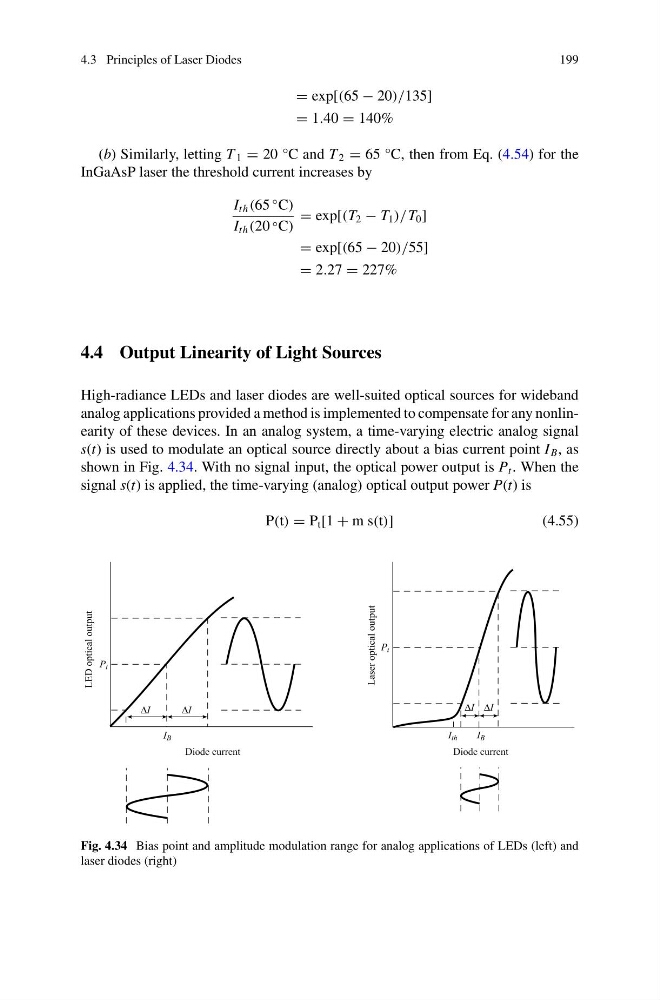
analog applications provided a method is implemented to compensate for any nonlinearity of these devices. In an analog system, a time-varying electric analog signal
s(t) is used to modulate an optical source directly about a bias current point I B , as
shown in Fig. 4.34. With no signal input, the optical power output is P t . When the
signal s(t) is applied, the time-varying (analog) optical output power P(t) is
P(t) = P t [1 + m s(t)]
(4.55)
Fig. 4.34 Bias point and amplitude modulation range for analog applications of LEDs (left) and
laser diodes (right)
199
= exp[(65 − 20)/135]
= 1.40 = 140%
(b) Similarly, letting T 1 = 20 °C and T 2 = 65 °C, then from Eq. (4.54) for the
InGaAsP laser the threshold current increases by
I th (65
◦ C)
I th (20 ◦ C)
= exp[(T 2 − T 1 )/T 0 ]
= exp[(65 − 20)/55]
= 2.27 = 227%
4.4 Output Linearity of Light Sources
High-radiance LEDs and laser diodes are well-suited optical sources for wideband
analog applications provided a method is implemented to compensate for any nonlinearity of these devices. In an analog system, a time-varying electric analog signal
s(t) is used to modulate an optical source directly about a bias current point I B , as
shown in Fig. 4.34. With no signal input, the optical power output is P t . When the
signal s(t) is applied, the time-varying (analog) optical output power P(t) is
P(t) = P t [1 + m s(t)]
(4.55)
Fig. 4.34 Bias point and amplitude modulation range for analog applications of LEDs (left) and
laser diodes (right)