

130
3 Optical Signal Attenuation and Dispersion
D(1550) =
λS 0
4
1 −
λ 0
λ
4
=
(1550)(0.092)
4
1 −
1310
1550
4
= 17.5 ps/(nm - km)
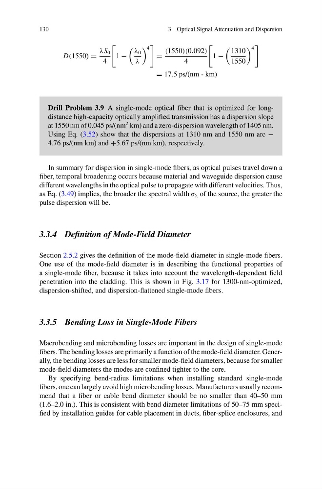
Drill Problem 3.9 A single-mode optical fiber that is optimized for longdistance high-capacity optically amplified transmission has a dispersion slope
at 1550 nm of 0.045 ps/(nm
2 km) and a zero-dispersion wavelength of 1405 nm.
Using Eq. (3.52) show that the dispersions at 1310 nm and 1550 nm are −
4.76 ps/(nm km) and +5.67 ps/(nm km), respectively.
In summary for dispersion in single-mode fibers, as optical pulses travel down a
fiber, temporal broadening occurs because material and waveguide dispersion cause
different wavelengths in the optical pulse to propagate with different velocities. Thus,
as Eq. (3.49) implies, the broader the spectral width σ λ of the source, the greater the
pulse dispersion will be.
3.3.4 Definition of Mode-Field Diameter
Section 2.5.2 gives the definition of the mode-field diameter in single-mode fibers.
One use of the mode-field diameter is in describing the functional properties of
a single-mode fiber, because it takes into account the wavelength-dependent field
penetration into the cladding. This is shown in Fig. 3.17 for 1300-nm-optimized,
dispersion-shifted, and dispersion-flattened single-mode fibers.
3.3.5 Bending Loss in Single-Mode Fibers
Macrobending and microbending losses are important in the design of single-mode
fibers. The bending losses are primarily a function of the mode-field diameter. Generally, the bending losses are less for smaller mode-field diameters, because for smaller
mode-field diameters the modes are confined tighter to the core.
By specifying bend-radius limitations when installing standard single-mode
fibers, one can largely avoid high microbending losses. Manufacturers usually recommend that a fiber or cable bend diameter should be no smaller than 40–50 mm
(1.6–2.0 in.). This is consistent with bend diameter limitations of 50–75 mm specified by installation guides for cable placement in ducts, fiber-splice enclosures, and
3 Optical Signal Attenuation and Dispersion
D(1550) =
λS 0
4
1 −
λ 0
λ
4
=
(1550)(0.092)
4
1 −
1310
1550
4
= 17.5 ps/(nm - km)
Drill Problem 3.9 A single-mode optical fiber that is optimized for longdistance high-capacity optically amplified transmission has a dispersion slope
at 1550 nm of 0.045 ps/(nm
2 km) and a zero-dispersion wavelength of 1405 nm.
Using Eq. (3.52) show that the dispersions at 1310 nm and 1550 nm are −
4.76 ps/(nm km) and +5.67 ps/(nm km), respectively.
In summary for dispersion in single-mode fibers, as optical pulses travel down a
fiber, temporal broadening occurs because material and waveguide dispersion cause
different wavelengths in the optical pulse to propagate with different velocities. Thus,
as Eq. (3.49) implies, the broader the spectral width σ λ of the source, the greater the
pulse dispersion will be.
3.3.4 Definition of Mode-Field Diameter
Section 2.5.2 gives the definition of the mode-field diameter in single-mode fibers.
One use of the mode-field diameter is in describing the functional properties of
a single-mode fiber, because it takes into account the wavelength-dependent field
penetration into the cladding. This is shown in Fig. 3.17 for 1300-nm-optimized,
dispersion-shifted, and dispersion-flattened single-mode fibers.
3.3.5 Bending Loss in Single-Mode Fibers
Macrobending and microbending losses are important in the design of single-mode
fibers. The bending losses are primarily a function of the mode-field diameter. Generally, the bending losses are less for smaller mode-field diameters, because for smaller
mode-field diameters the modes are confined tighter to the core.
By specifying bend-radius limitations when installing standard single-mode
fibers, one can largely avoid high microbending losses. Manufacturers usually recommend that a fiber or cable bend diameter should be no smaller than 40–50 mm
(1.6–2.0 in.). This is consistent with bend diameter limitations of 50–75 mm specified by installation guides for cable placement in ducts, fiber-splice enclosures, and