

3.3 Design and Characteristics of SMFs
125
the nonzero dispersion-shifted fiber (NZDSF). These fibers have a small amount of
either all positive or all negative dispersion throughout the C-band. A typical positive
chromatic dispersion value for a NZDSF is 4.5 ps/(nm km) at 1550 nm.
Among the NZDSF types is a single-mode optical fiber with a larger effective
core area. The larger core areas reduce the effects of fiber nonlinearities, which
otherwise limit system capacities of transmission systems that have densely spaced
WDM channels. Figure 3.13d gives two examples of the index profile for these largeeffective-area (LEA) fibers. Whereas standard single-mode fibers have effective core
areas of about 55 μm
2 , these profiles yield values greater than 100 μm
2 .
An alternative fiber design concept is to distribute the dispersion minimum over
a wider spectral range. This approach is known as dispersion flattening. Dispersionflattened fibers are more complex to design than dispersion-shifted fibers, because
dispersion must be considered over a much broader range of wavelengths. However,
they offer desirable characteristics over a wide span of wavelengths. Figure 3.13c
shows typical cross-sectional refractive-index profiles. Typical waveguide dispersion
curves for three types of fiber are depicted in Fig. 3.14a. Figure 3.14b gives the
resultant total material plus waveguide dispersion characteristics.
3.3.2 Concept of Cutoff Wavelength
The cutoff wavelength of the first higher-order mode (LP 11 ) is an important transmission parameter for single-mode fibers because it separates the single- mode from
the multimode regions. Recall from Eq. (2.27) that single-mode operation occurs
above the theoretical cutoff wavelength given by
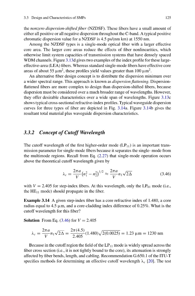
λ c =
2πa
V
n
2
1 − n
2
2
1/2 ≈
2πa
V
n 1
√
2
(3.46)
with V = 2.405 for step-index fibers. At this wavelength, only the LP 01 mode (i.e.,
the HE 11 mode) should propagate in the fiber.
Example 3.14 A given step-index fiber has a core refractive index of 1.480, a core
radius equal to 4.5 μm, and a core-cladding index difference of 0.25%. What is the
cutoff wavelength for this fiber?
Solution From Eq. (3.46) for V = 2.405
λ c =
2πa
V
n 1
√
2 =
2π(4.5)
2.405
(1.480)
2(0.0025) = 1.23 μm = 1230 nm
Because in the cutoff region the field of the LP 11 mode is widely spread across the
fiber cross section (i.e., it is not tightly bound to the core), its attenuation is strongly
affected by fiber bends, length, and cabling. Recommendation G.650.1 of the ITU-T
specifies methods for determining an effective cutoff wavelength λ c [20]. The test
125
the nonzero dispersion-shifted fiber (NZDSF). These fibers have a small amount of
either all positive or all negative dispersion throughout the C-band. A typical positive
chromatic dispersion value for a NZDSF is 4.5 ps/(nm km) at 1550 nm.
Among the NZDSF types is a single-mode optical fiber with a larger effective
core area. The larger core areas reduce the effects of fiber nonlinearities, which
otherwise limit system capacities of transmission systems that have densely spaced
WDM channels. Figure 3.13d gives two examples of the index profile for these largeeffective-area (LEA) fibers. Whereas standard single-mode fibers have effective core
areas of about 55 μm
2 , these profiles yield values greater than 100 μm
2 .
An alternative fiber design concept is to distribute the dispersion minimum over
a wider spectral range. This approach is known as dispersion flattening. Dispersionflattened fibers are more complex to design than dispersion-shifted fibers, because
dispersion must be considered over a much broader range of wavelengths. However,
they offer desirable characteristics over a wide span of wavelengths. Figure 3.13c
shows typical cross-sectional refractive-index profiles. Typical waveguide dispersion
curves for three types of fiber are depicted in Fig. 3.14a. Figure 3.14b gives the
resultant total material plus waveguide dispersion characteristics.
3.3.2 Concept of Cutoff Wavelength
The cutoff wavelength of the first higher-order mode (LP 11 ) is an important transmission parameter for single-mode fibers because it separates the single- mode from
the multimode regions. Recall from Eq. (2.27) that single-mode operation occurs
above the theoretical cutoff wavelength given by
λ c =
2πa
V
n
2
1 − n
2
2
1/2 ≈
2πa
V
n 1
√
2
(3.46)
with V = 2.405 for step-index fibers. At this wavelength, only the LP 01 mode (i.e.,
the HE 11 mode) should propagate in the fiber.
Example 3.14 A given step-index fiber has a core refractive index of 1.480, a core
radius equal to 4.5 μm, and a core-cladding index difference of 0.25%. What is the
cutoff wavelength for this fiber?
Solution From Eq. (3.46) for V = 2.405
λ c =
2πa
V
n 1
√
2 =
2π(4.5)
2.405
(1.480)
2(0.0025) = 1.23 μm = 1230 nm
Because in the cutoff region the field of the LP 11 mode is widely spread across the
fiber cross section (i.e., it is not tightly bound to the core), its attenuation is strongly
affected by fiber bends, length, and cabling. Recommendation G.650.1 of the ITU-T
specifies methods for determining an effective cutoff wavelength λ c [20]. The test