

3.1 Fiber Attenuation
107
where α 1 and α 2 are the axial and cladding attenuation coefficients, respectively, and
the n terms are defined by Eq. (2.38). The loss encountered by a given mode is then
α gi =
∞
0 α(r ) p(r ) r dr
∞
0 p(r ) r dr
(3.17)
where p(r) is the power density of that mode at r. The complexity of the multimode
waveguide has prevented an experimental correlation with a model. However, it has
generally been observed that the loss increases with increasing mode number.
3.2 Optical Signal Dispersion Effects
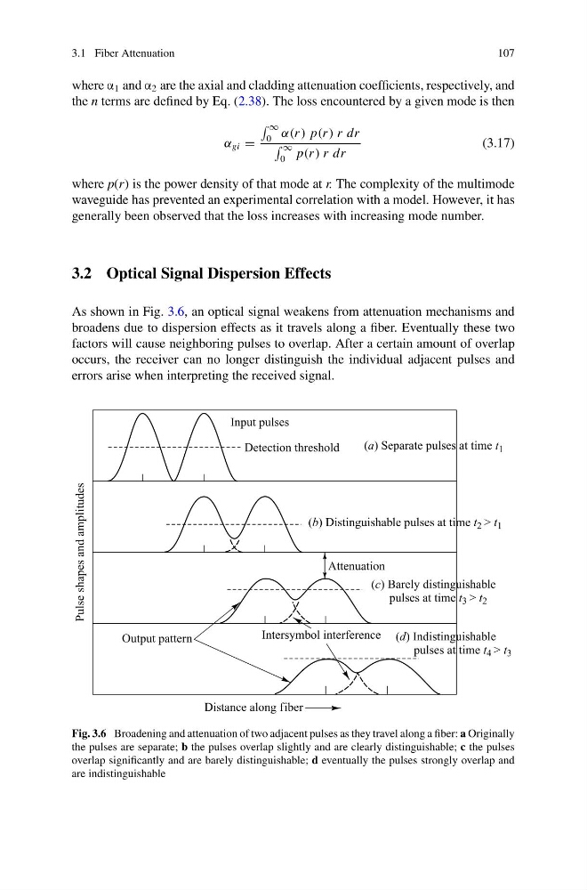
As shown in Fig. 3.6, an optical signal weakens from attenuation mechanisms and
broadens due to dispersion effects as it travels along a fiber. Eventually these two
factors will cause neighboring pulses to overlap. After a certain amount of overlap
occurs, the receiver can no longer distinguish the individual adjacent pulses and
errors arise when interpreting the received signal.
Fig. 3.6 Broadening and attenuation of two adjacent pulses as they travel along a fiber: a Originally
the pulses are separate; b the pulses overlap slightly and are clearly distinguishable; c the pulses
overlap significantly and are barely distinguishable; d eventually the pulses strongly overlap and
are indistinguishable
107
where α 1 and α 2 are the axial and cladding attenuation coefficients, respectively, and
the n terms are defined by Eq. (2.38). The loss encountered by a given mode is then
α gi =
∞
0 α(r ) p(r ) r dr
∞
0 p(r ) r dr
(3.17)
where p(r) is the power density of that mode at r. The complexity of the multimode
waveguide has prevented an experimental correlation with a model. However, it has
generally been observed that the loss increases with increasing mode number.
3.2 Optical Signal Dispersion Effects
As shown in Fig. 3.6, an optical signal weakens from attenuation mechanisms and
broadens due to dispersion effects as it travels along a fiber. Eventually these two
factors will cause neighboring pulses to overlap. After a certain amount of overlap
occurs, the receiver can no longer distinguish the individual adjacent pulses and
errors arise when interpreting the received signal.
Fig. 3.6 Broadening and attenuation of two adjacent pulses as they travel along a fiber: a Originally
the pulses are separate; b the pulses overlap slightly and are clearly distinguishable; c the pulses
overlap significantly and are barely distinguishable; d eventually the pulses strongly overlap and
are indistinguishable