

88
2 Optical Fiber Structures and Light Guiding Principles
T ⊥ =
n 2 cos θ 2
n 1 cos θ 1
E 0t
E 0i
2
x
= T x =
n 2 cos θ 2
n 1 cos θ 1
t
2
x
(2.52)
T || =
n 2 cos θ 2
n 1 cos θ 1
E 0t
E 0i
2
y
= T y =
n 2 cos θ 2
n 1 cos θ 1
t
2
y
(2.53)
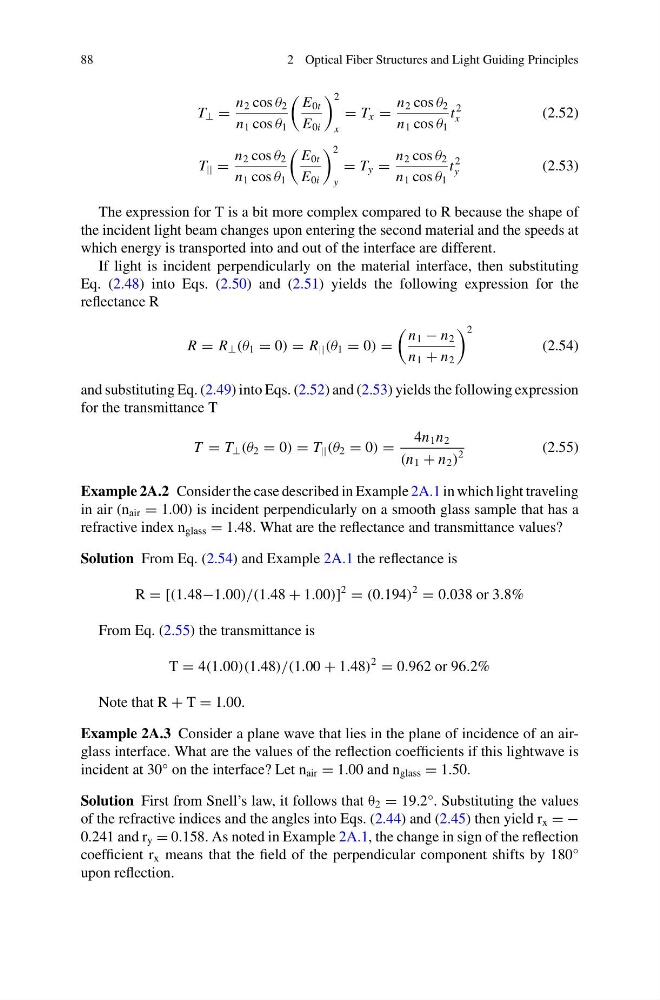
The expression for T is a bit more complex compared to R because the shape of
the incident light beam changes upon entering the second material and the speeds at
which energy is transported into and out of the interface are different.
If light is incident perpendicularly on the material interface, then substituting
Eq. (2.48) into Eqs. (2.50) and (2.51) yields the following expression for the
reflectance R
R = R ⊥ (θ 1 = 0) = R || (θ 1 = 0) =
n 1 − n 2
n 1 + n 2
2
(2.54)
and substituting Eq. (2.49) into Eqs. (2.52) and (2.53) yields the following expression
for the transmittance T
T = T ⊥ (θ 2 = 0) = T || (θ 2 = 0) =
4n 1 n 2
(n 1 + n 2 )
2
(2.55)
Example 2A.2 Consider the case described in Example 2A.1 in which light traveling
in air (n air = 1.00) is incident perpendicularly on a smooth glass sample that has a
refractive index n glass = 1.48. What are the reflectance and transmittance values?
Solution From Eq. (2.54) and Example 2A.1 the reflectance is
R = [(1.48−1.00)/(1.48 + 1.00)]
2
= (0.194)
2
= 0.038 or 3.8%
From Eq. (2.55) the transmittance is
T = 4(1.00)(1.48)/(1.00 + 1.48)
2
= 0.962 or 96.2%
Note that R + T = 1.00.
Example 2A.3 Consider a plane wave that lies in the plane of incidence of an airglass interface. What are the values of the reflection coefficients if this lightwave is
incident at 30° on the interface? Let n air = 1.00 and n glass = 1.50.
Solution First from Snell’s law, it follows that θ 2 = 19.2°. Substituting the values
of the refractive indices and the angles into Eqs. (2.44) and (2.45) then yield r x = −
0.241 and r y = 0.158. As noted in Example 2A.1, the change in sign of the reflection
coefficient r x means that the field of the perpendicular component shifts by 180°
upon reflection.
2 Optical Fiber Structures and Light Guiding Principles
T ⊥ =
n 2 cos θ 2
n 1 cos θ 1
E 0t
E 0i
2
x
= T x =
n 2 cos θ 2
n 1 cos θ 1
t
2
x
(2.52)
T || =
n 2 cos θ 2
n 1 cos θ 1
E 0t
E 0i
2
y
= T y =
n 2 cos θ 2
n 1 cos θ 1
t
2
y
(2.53)
The expression for T is a bit more complex compared to R because the shape of
the incident light beam changes upon entering the second material and the speeds at
which energy is transported into and out of the interface are different.
If light is incident perpendicularly on the material interface, then substituting
Eq. (2.48) into Eqs. (2.50) and (2.51) yields the following expression for the
reflectance R
R = R ⊥ (θ 1 = 0) = R || (θ 1 = 0) =
n 1 − n 2
n 1 + n 2
2
(2.54)
and substituting Eq. (2.49) into Eqs. (2.52) and (2.53) yields the following expression
for the transmittance T
T = T ⊥ (θ 2 = 0) = T || (θ 2 = 0) =
4n 1 n 2
(n 1 + n 2 )
2
(2.55)
Example 2A.2 Consider the case described in Example 2A.1 in which light traveling
in air (n air = 1.00) is incident perpendicularly on a smooth glass sample that has a
refractive index n glass = 1.48. What are the reflectance and transmittance values?
Solution From Eq. (2.54) and Example 2A.1 the reflectance is
R = [(1.48−1.00)/(1.48 + 1.00)]
2
= (0.194)
2
= 0.038 or 3.8%
From Eq. (2.55) the transmittance is
T = 4(1.00)(1.48)/(1.00 + 1.48)
2
= 0.962 or 96.2%
Note that R + T = 1.00.
Example 2A.3 Consider a plane wave that lies in the plane of incidence of an airglass interface. What are the values of the reflection coefficients if this lightwave is
incident at 30° on the interface? Let n air = 1.00 and n glass = 1.50.
Solution First from Snell’s law, it follows that θ 2 = 19.2°. Substituting the values
of the refractive indices and the angles into Eqs. (2.44) and (2.45) then yield r x = −
0.241 and r y = 0.158. As noted in Example 2A.1, the change in sign of the reflection
coefficient r x means that the field of the perpendicular component shifts by 180°
upon reflection.