

86
2 Optical Fiber Structures and Light Guiding Principles
found by solving Maxwell’s equations for a dielectric medium subject to the electromagnetic field boundary conditions at the core-cladding interface of an optical fiber.
The analysis is rather complex because the boundary conditions create a coupling
between the longitudinal components of the E and H fields, which leads to hybrid
mode solutions.
However, in place of a lengthy exact analysis for the modes of a fiber, a simpler
but highly accurate approximation can be used, based on the principle that in a
typical step-index fiber the difference between the indices of refraction of the core
and cladding is very small. This is the weakly guiding fiber approximation that has
been used successfully for evaluating optical fiber waveguide characteristics.
Appendix: The Fresnel Equations
One can consider unpolarized light as consisting of two orthogonal plane polarization components. For analyzing reflected and refracted light, one component can be
chosen to lie in the plane of incidence (the plane containing the incident and reflected
rays, which here is taken to be the yz-plane) and the other of which lies in a plane
perpendicular to the plane of incidence (the xz-plane). For example, these can be the
E x and E y components of the electric field vector. These then are designated as the
perpendicular polarization (E x ) and the parallel polarization (E y ) components with
maximum amplitudes E 0x and E 0y , respectively.
When an unpolarized light beam traveling in air impinges on a nonmetallic surface
such as a glass material, part of the beam (designated by E 0r ) is reflected and part
of the beam (designated by E 0t ) is refracted and transmitted into the target material.
The reflected beam is partially polarized and at a specific angle (known as Brewster’s
angle) the reflected light is completely perpendicularly polarized, so that (E 0r ) y =
0. This condition holds when the angle of incidence is such that θ 1 + θ 2 = 90° (see
Fig. 2.6 for the angle definitions). The parallel component of the refracted beam is
transmitted entirely into the target material, whereas the perpendicular component
is only partially refracted. How much of the refracted light is polarized depends on
the angle at which the light approaches the surface and on the material composition.
The amount of light of each polarization type that is reflected and refracted at a
material interface can be calculated using a set of equations known as the Fresnel
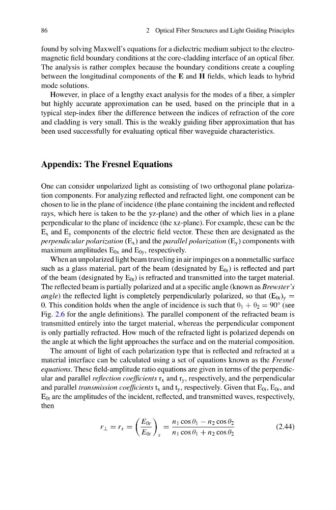
equations. These field-amplitude ratio equations are given in terms of the perpendicular and parallel reflection coefficients r x and r y , respectively, and the perpendicular
and parallel transmission coefficients t x and t y , respectively. Given that E 0i , E 0r , and
E 0t are the amplitudes of the incident, reflected, and transmitted waves, respectively,
then
r ⊥ = r x =
E 0r
E 0i
x
=
n 1 cos θ 1 − n 2 cos θ 2
n 1 cos θ 1 + n 2 cos θ 2
(2.44)
2 Optical Fiber Structures and Light Guiding Principles
found by solving Maxwell’s equations for a dielectric medium subject to the electromagnetic field boundary conditions at the core-cladding interface of an optical fiber.
The analysis is rather complex because the boundary conditions create a coupling
between the longitudinal components of the E and H fields, which leads to hybrid
mode solutions.
However, in place of a lengthy exact analysis for the modes of a fiber, a simpler
but highly accurate approximation can be used, based on the principle that in a
typical step-index fiber the difference between the indices of refraction of the core
and cladding is very small. This is the weakly guiding fiber approximation that has
been used successfully for evaluating optical fiber waveguide characteristics.
Appendix: The Fresnel Equations
One can consider unpolarized light as consisting of two orthogonal plane polarization components. For analyzing reflected and refracted light, one component can be
chosen to lie in the plane of incidence (the plane containing the incident and reflected
rays, which here is taken to be the yz-plane) and the other of which lies in a plane
perpendicular to the plane of incidence (the xz-plane). For example, these can be the
E x and E y components of the electric field vector. These then are designated as the
perpendicular polarization (E x ) and the parallel polarization (E y ) components with
maximum amplitudes E 0x and E 0y , respectively.
When an unpolarized light beam traveling in air impinges on a nonmetallic surface
such as a glass material, part of the beam (designated by E 0r ) is reflected and part
of the beam (designated by E 0t ) is refracted and transmitted into the target material.
The reflected beam is partially polarized and at a specific angle (known as Brewster’s
angle) the reflected light is completely perpendicularly polarized, so that (E 0r ) y =
0. This condition holds when the angle of incidence is such that θ 1 + θ 2 = 90° (see
Fig. 2.6 for the angle definitions). The parallel component of the refracted beam is
transmitted entirely into the target material, whereas the perpendicular component
is only partially refracted. How much of the refracted light is polarized depends on
the angle at which the light approaches the surface and on the material composition.
The amount of light of each polarization type that is reflected and refracted at a
material interface can be calculated using a set of equations known as the Fresnel
equations. These field-amplitude ratio equations are given in terms of the perpendicular and parallel reflection coefficients r x and r y , respectively, and the perpendicular
and parallel transmission coefficients t x and t y , respectively. Given that E 0i , E 0r , and
E 0t are the amplitudes of the incident, reflected, and transmitted waves, respectively,
then
r ⊥ = r x =
E 0r
E 0i
x
=
n 1 cos θ 1 − n 2 cos θ 2
n 1 cos θ 1 + n 2 cos θ 2
(2.44)