

10 Circularly Polarized Luminescence (CPL) Based on Planar …
367
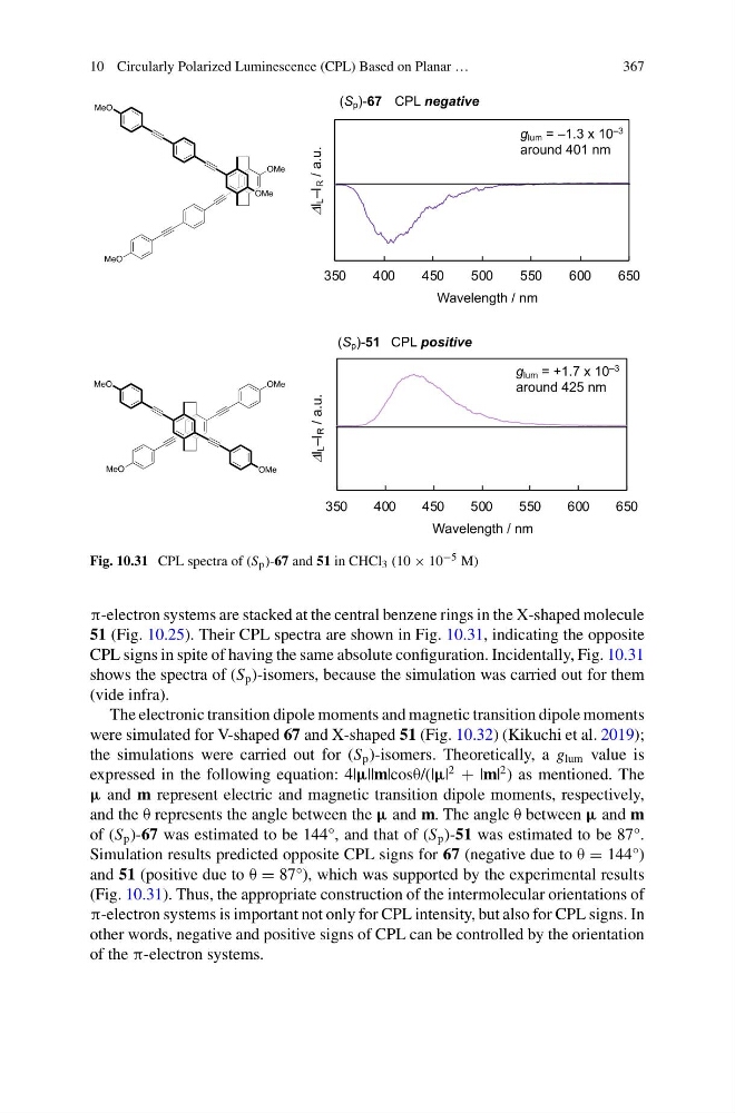
Fig. 10.31 CPL spectra of (S p )-67 and 51 in CHCl 3 (10 × 10 −5 M)
π-electron systems are stacked at the central benzene rings in the X-shaped molecule
51 (Fig. 10.25). Their CPL spectra are shown in Fig. 10.31, indicating the opposite
CPL signs in spite of having the same absolute configuration. Incidentally, Fig. 10.31
shows the spectra of (S p )-isomers, because the simulation was carried out for them
(vide infra).
The electronic transition dipole moments and magnetic transition dipole moments
were simulated for V-shaped 67 and X-shaped 51 (Fig. 10.32) (Kikuchi et al. 2019);
the simulations were carried out for (S p )-isomers. Theoretically, a g lum value is
expressed in the following equation: 4|μ||m|cosθ/(|μ|
2
+ |m|
2 ) as mentioned. The
μ and m represent electric and magnetic transition dipole moments, respectively,
and the θ represents the angle between the μ and m. The angle θ between μ and m
of (S p )-67 was estimated to be 144°, and that of (S p )-51 was estimated to be 87°.
Simulation results predicted opposite CPL signs for 67 (negative due to θ = 144°)
and 51 (positive due to θ = 87°), which was supported by the experimental results
(Fig. 10.31). Thus, the appropriate construction of the intermolecular orientations of
π-electron systems is important not only for CPL intensity, but also for CPL signs. In
other words, negative and positive signs of CPL can be controlled by the orientation
of the π-electron systems.
367
Fig. 10.31 CPL spectra of (S p )-67 and 51 in CHCl 3 (10 × 10 −5 M)
π-electron systems are stacked at the central benzene rings in the X-shaped molecule
51 (Fig. 10.25). Their CPL spectra are shown in Fig. 10.31, indicating the opposite
CPL signs in spite of having the same absolute configuration. Incidentally, Fig. 10.31
shows the spectra of (S p )-isomers, because the simulation was carried out for them
(vide infra).
The electronic transition dipole moments and magnetic transition dipole moments
were simulated for V-shaped 67 and X-shaped 51 (Fig. 10.32) (Kikuchi et al. 2019);
the simulations were carried out for (S p )-isomers. Theoretically, a g lum value is
expressed in the following equation: 4|μ||m|cosθ/(|μ|
2
+ |m|
2 ) as mentioned. The
μ and m represent electric and magnetic transition dipole moments, respectively,
and the θ represents the angle between the μ and m. The angle θ between μ and m
of (S p )-67 was estimated to be 144°, and that of (S p )-51 was estimated to be 87°.
Simulation results predicted opposite CPL signs for 67 (negative due to θ = 144°)
and 51 (positive due to θ = 87°), which was supported by the experimental results
(Fig. 10.31). Thus, the appropriate construction of the intermolecular orientations of
π-electron systems is important not only for CPL intensity, but also for CPL signs. In
other words, negative and positive signs of CPL can be controlled by the orientation
of the π-electron systems.