

8.7.1.4 Image focusing
One of the major obstacles in imaging ellipsometry is that only the center
of the image is in focus due to the large incident angle of the light beam.
To compensate for this limited focus area, a scanner can be incorporated into imaging ellipsometer instruments. The image may then be
taken at several different positions, and the computer software combines
these images into one focused image of the entire sample. An alternative
approach has been to use the Scheimpflug method, which is an optical
technique that allows the entire sample to be placed in focus by tilting the
lens to a certain degree, called the Scheimpflug line.
8.7.1.5 Resolution of an imaging ellipsometer
The lateral (x,y) resolution for an imaging ellipsometer as described above
is generally limited by the resolving power of the CCD camera and is
usually on the order of a few microns. The depth (z) resolution, on the
other hand, is comparable to conventional ellipsometry at a few tenths of
a nanometer. Because of its nondestructive nature, compatibility with a
wide variety of sample types, and excellent temporal and depth resolution,
imaging ellipsometry is a powerful technique to image nanostructures and
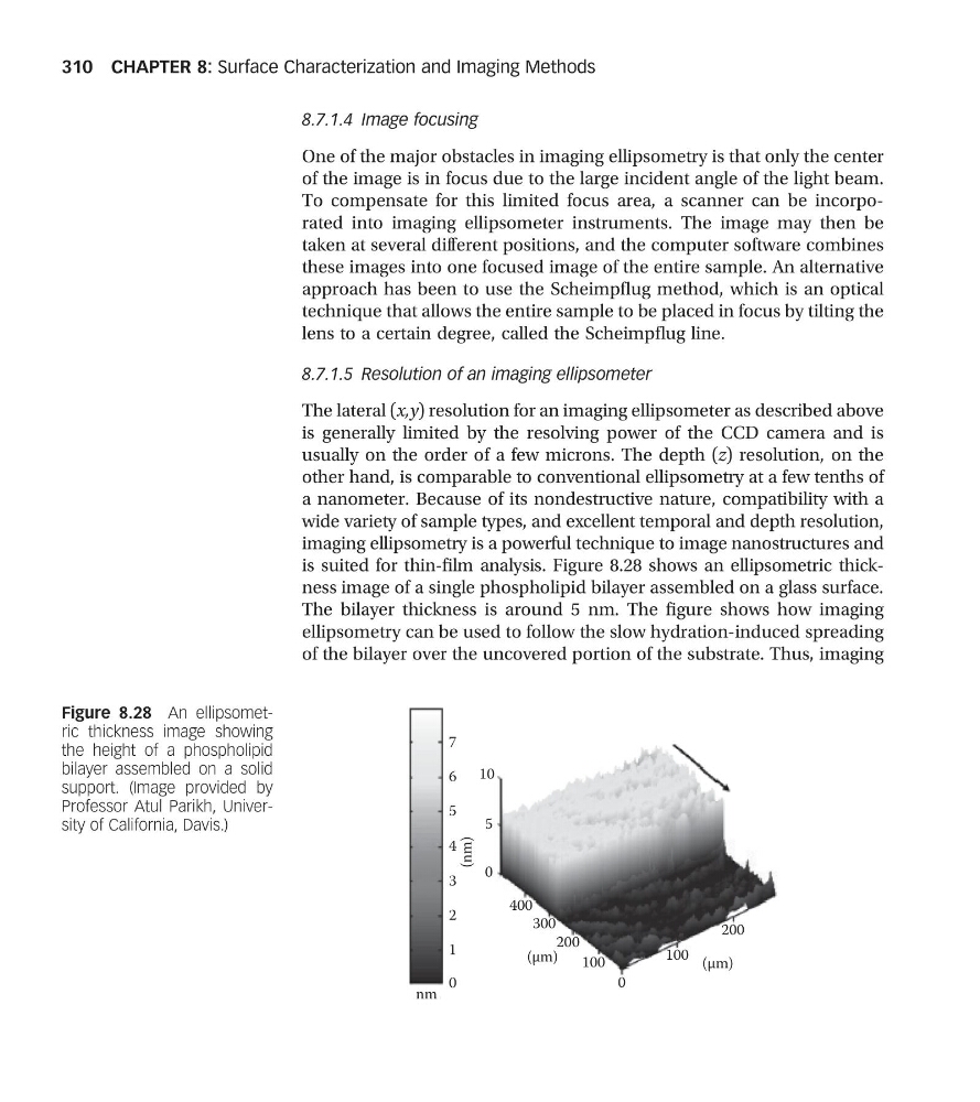
is suited for thin-film analysis. Figure 8.28 shows an ellipsometric thickness image of a single phospholipid bilayer assembled on a glass surface.
The bilayer thickness is around 5 nm. The figure shows how imaging
ellipsometry can be used to follow the slow hydration-induced spreading
of the bilayer over the uncovered portion of the substrate. Thus, imaging
7
6
5
4
(nm)
3
2
1
0
nm
(μm)
(μm)
0
400
300
200
100
100
200
0
5
10
Figure 8.28 An ellipsometric thickness image showing
the height of a phospholipid
bilayer assembled on a solid
support. (Image provided by
Professor Atul Parikh, University of California, Davis.)
CHAPTER 8: Surface Characterization and Imaging Methods
310
One of the major obstacles in imaging ellipsometry is that only the center
of the image is in focus due to the large incident angle of the light beam.
To compensate for this limited focus area, a scanner can be incorporated into imaging ellipsometer instruments. The image may then be
taken at several different positions, and the computer software combines
these images into one focused image of the entire sample. An alternative
approach has been to use the Scheimpflug method, which is an optical
technique that allows the entire sample to be placed in focus by tilting the
lens to a certain degree, called the Scheimpflug line.
8.7.1.5 Resolution of an imaging ellipsometer
The lateral (x,y) resolution for an imaging ellipsometer as described above
is generally limited by the resolving power of the CCD camera and is
usually on the order of a few microns. The depth (z) resolution, on the
other hand, is comparable to conventional ellipsometry at a few tenths of
a nanometer. Because of its nondestructive nature, compatibility with a
wide variety of sample types, and excellent temporal and depth resolution,
imaging ellipsometry is a powerful technique to image nanostructures and
is suited for thin-film analysis. Figure 8.28 shows an ellipsometric thickness image of a single phospholipid bilayer assembled on a glass surface.
The bilayer thickness is around 5 nm. The figure shows how imaging
ellipsometry can be used to follow the slow hydration-induced spreading
of the bilayer over the uncovered portion of the substrate. Thus, imaging
7
6
5
4
(nm)
3
2
1
0
nm
(μm)
(μm)
0
400
300
200
100
100
200
0
5
10
Figure 8.28 An ellipsometric thickness image showing
the height of a phospholipid
bilayer assembled on a solid
support. (Image provided by
Professor Atul Parikh, University of California, Davis.)
CHAPTER 8: Surface Characterization and Imaging Methods
310