

612
V. Ya. Podhurska et al.
Table 2 Characteristics of wear and arc resistances of the studied materials
Variant
Weight losses m, mg
Defects parameters for arcs of various power
μF
d, μm
h, μm
Body
Counterbody
300
600
300
600
1
0.2
12.4
900
1430
11
13
2
0.1
21.1
1100
1500
14
8
3
0.5
22.8
960
1450
5
7
4
0.2
8.5
1050
1550
9
9
5
0.1
1.2
1000
1320
7
6
6
0.3
1.1
850
1300
4
8
7
0.3
1.7
814
1145
10
14
8
6.0
10.5
813
1200
42
76
6) are obtained and copper wear is reduced by an order of magnitude and more, like
in the case of testing the material obtained by two-step technology (Table 2; variants
5, 6, 7). At the same time, copper wears out 9 times less than in the case of contact
with an aluminum alloy [12].
It should be noted that the tendency to pronounced brittle fracture of the materials
of variants 1 and 8 causes the appearance in a contact zone of the friction couple
containing abrasive particles, which reinforces the wear of the copper counterbody.
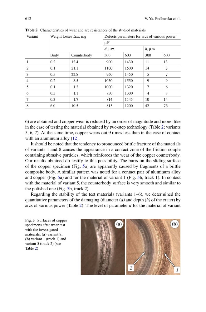
Our results obtained do testify to this possibility. The burrs on the sliding surface
of the copper specimen (Fig. 5a) are apparently caused by fragments of a brittle
composite body. A similar pattern was noted for a contact pair of aluminum alloy
and copper (Fig. 5a) and for the material of variant 1 (Fig. 5b, track 1). In contact
with the material of variant 5, the counterbody surface is very smooth and similar to
the polished one (Fig. 5b, track 2).
Regarding the stability of the test materials (variants 1–6), we determined the
quantitative parameters of the damaging (diameter (d) and depth (h) of the crater) by
arcs of various power (Table 2). The level of parameter d for the material of variant
Fig. 5 Surfaces of copper
specimens after wear test
with the investigated
materials: (a) variant 8;
(b) variant 1 (track 1) and
variant 5 (track 2) (see
Table 2)