

212
A. E. Artyukhov et al.
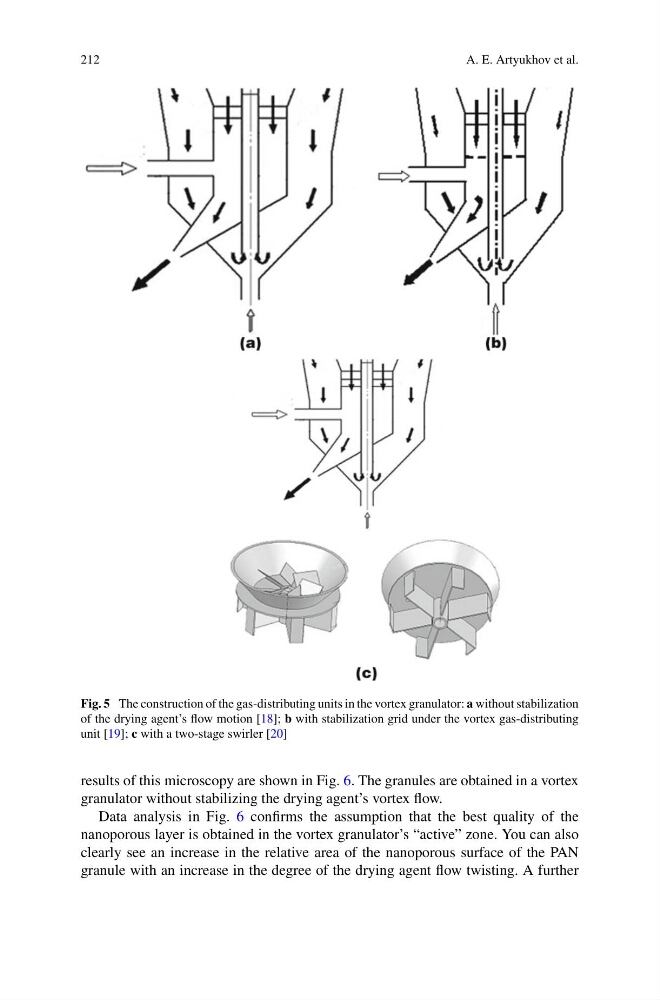
Fig. 5 The construction of the gas-distributing units in the vortex granulator: a without stabilization
of the drying agent’s flow motion [18]; b with stabilization grid under the vortex gas-distributing
unit [19]; c with a two-stage swirler [20]
results of this microscopy are shown in Fig. 6. The granules are obtained in a vortex
granulator without stabilizing the drying agent’s vortex flow.
Data analysis in Fig. 6 confirms the assumption that the best quality of the
nanoporous layer is obtained in the vortex granulator’s “active” zone. You can also
clearly see an increase in the relative area of the nanoporous surface of the PAN
granule with an increase in the degree of the drying agent flow twisting. A further
A. E. Artyukhov et al.
Fig. 5 The construction of the gas-distributing units in the vortex granulator: a without stabilization
of the drying agent’s flow motion [18]; b with stabilization grid under the vortex gas-distributing
unit [19]; c with a two-stage swirler [20]
results of this microscopy are shown in Fig. 6. The granules are obtained in a vortex
granulator without stabilizing the drying agent’s vortex flow.
Data analysis in Fig. 6 confirms the assumption that the best quality of the
nanoporous layer is obtained in the vortex granulator’s “active” zone. You can also
clearly see an increase in the relative area of the nanoporous surface of the PAN
granule with an increase in the degree of the drying agent flow twisting. A further