

49
Analysis and Design of a Bionic Fitness Cycle
TABLE 3.2
Corresponding Signals for the Place
of the Pedal Crank
Corresponding
Place of Pedal Crank
Signal
Area I
101
Area II
001
Area III
000
Area IV
100
Area V
110
Area VI
010
Area VII
011
Area VIII
111
START
Delay 2 seconds
Speed ! = 0
N
Y
Collect the pulse number of
feet and hands
Left foot ^ right hand
Normal mode
Bionic mode
Show the mode
L_H_P == 0
&&
R_H_P== 0
L_H_P! = 0
&&
R_H_P!= 0
11 appear
from
hands’ flags
011 appear from
flags of feet
000 appear from
flags of feet
Y
Y
Y
N
N
N
Y
N
N
Y
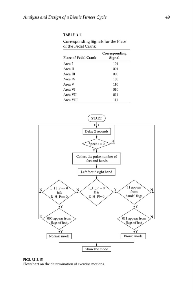
FIGURE 3.15
Flowchart on the determination of exercise motions.
Analysis and Design of a Bionic Fitness Cycle
TABLE 3.2
Corresponding Signals for the Place
of the Pedal Crank
Corresponding
Place of Pedal Crank
Signal
Area I
101
Area II
001
Area III
000
Area IV
100
Area V
110
Area VI
010
Area VII
011
Area VIII
111
START
Delay 2 seconds
Speed ! = 0
N
Y
Collect the pulse number of
feet and hands
Left foot ^ right hand
Normal mode
Bionic mode
Show the mode
L_H_P == 0
&&
R_H_P== 0
L_H_P! = 0
&&
R_H_P!= 0
11 appear
from
hands’ flags
011 appear from
flags of feet
000 appear from
flags of feet
Y
Y
Y
N
N
N
Y
N
N
Y
FIGURE 3.15
Flowchart on the determination of exercise motions.