

242
Biologically Inspired Robotics
The motor converts electric power into mechanical power to provide active
torque. Utilizing MR fluids, the clutch/brake transfers the torque generated
from the motor to the outside as a clutch or provides controllable semi-active
torque as a brake. Multiple functions can be achieved by applying current on
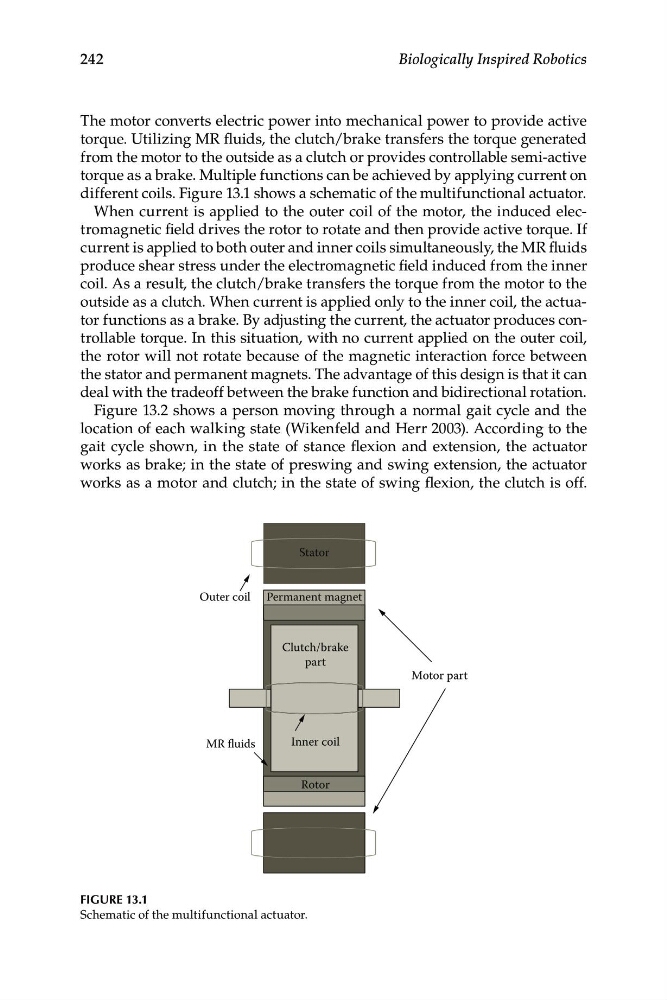
different coils. Figure 13.1 shows a schematic of the multifunctional actuator.
When current is applied to the outer coil of the motor, the induced electromagnetic field drives the rotor to rotate and then provide active torque. If
current is applied to both outer and inner coils simultaneously, the MR fluids
produce shear stress under the electromagnetic field induced from the inner
coil. As a result, the clutch/brake transfers the torque from the motor to the
outside as a clutch. When current is applied only to the inner coil, the actuator functions as a brake. By adjusting the current, the actuator produces controllable torque. In this situation, with no current applied on the outer coil,
the rotor will not rotate because of the magnetic interaction force between
the stator and permanent magnets. The advantage of this design is that it can
deal with the tradeoff between the brake function and bidirectional rotation.
Figure 13.2 shows a person moving through a normal gait cycle and the
location of each walking state (Wikenfeld and Herr 2003). According to the
gait cycle shown, in the state of stance flexion and extension, the actuator
works as brake; in the state of preswing and swing extension, the actuator
works as a motor and clutch; in the state of swing flexion, the clutch is off.
Motor part
Clutch/brake
part
Permanent magnet
Outer coil
Stator
Inner coil
Rotor
MR fluids
FIGURE 13.1
Schematic of the multifunctional actuator.
Biologically Inspired Robotics
The motor converts electric power into mechanical power to provide active
torque. Utilizing MR fluids, the clutch/brake transfers the torque generated
from the motor to the outside as a clutch or provides controllable semi-active
torque as a brake. Multiple functions can be achieved by applying current on
different coils. Figure 13.1 shows a schematic of the multifunctional actuator.
When current is applied to the outer coil of the motor, the induced electromagnetic field drives the rotor to rotate and then provide active torque. If
current is applied to both outer and inner coils simultaneously, the MR fluids
produce shear stress under the electromagnetic field induced from the inner
coil. As a result, the clutch/brake transfers the torque from the motor to the
outside as a clutch. When current is applied only to the inner coil, the actuator functions as a brake. By adjusting the current, the actuator produces controllable torque. In this situation, with no current applied on the outer coil,
the rotor will not rotate because of the magnetic interaction force between
the stator and permanent magnets. The advantage of this design is that it can
deal with the tradeoff between the brake function and bidirectional rotation.
Figure 13.2 shows a person moving through a normal gait cycle and the
location of each walking state (Wikenfeld and Herr 2003). According to the
gait cycle shown, in the state of stance flexion and extension, the actuator
works as brake; in the state of preswing and swing extension, the actuator
works as a motor and clutch; in the state of swing flexion, the clutch is off.
Motor part
Clutch/brake
part
Permanent magnet
Outer coil
Stator
Inner coil
Rotor
MR fluids
FIGURE 13.1
Schematic of the multifunctional actuator.