

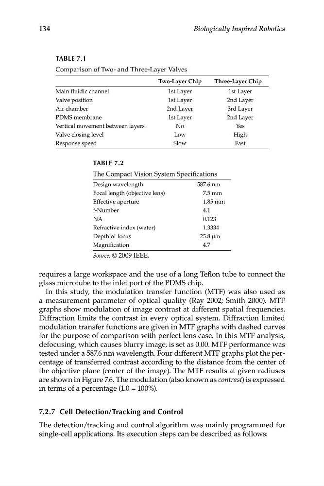
TABLE 7.1
Comparison of Two- and Three-Layer Valves
Two-Layer Chip
Three-Layer Chip
Main fluidic channel
1st Layer
1st Layer
Valve position
1st Layer
2nd Layer
Air chamber
2nd Layer
3rd Layer
PDMS membrane
1st Layer
2nd Layer
Vertical movement between layers
No
Yes
Valve closing level
Low
High
Response speed
Slow
Fast
TABLE 7.2
The Compact Vision System Specifications
Design wavelength
587.6 nm
Focal length (objective lens)
7.5 mm
Effective aperture
1.85 mm
f-Number
4.1
NA
0.123
Refractive index (water)
1.3334
Depth of focus
25.8 μm
Magnification
4.7
Source: © 2009 IEEE.
134
Biologically Inspired Robotics
requires a large workspace and the use of a long Teflon tube to connect the
glass microtube to the inlet port of the PDMS chip.
In this study, the modulation transfer function (MTF) was also used as
a measurement parameter of optical quality (Ray 2002; Smith 2000). MTF
graphs show modulation of image contrast at different spatial frequencies.
Diffraction limits the contrast in every optical system. Diffraction limited
modulation transfer functions are given in MTF graphs with dashed curves
for the purpose of comparison with perfect lens case. In this MTF analysis,
defocusing, which causes blurry image, is set as 0.00. MTF performance was
tested under a 587.6 nm wavelength. Four different MTF graphs plot the percentage of transferred contrast according to the distance from the center of
the objective plane (center of the image). The MTF results at given radiuses
are shown in Figure 7.6. The modulation (also known as contrast) is expressed
in terms of a percentage (1.0 = 100%).
7.2.7 Cell Detection/Tracking and Control
The detection/tracking and control algorithm was mainly programmed for
single-cell applications. Its execution steps can be described as follows:
Comparison of Two- and Three-Layer Valves
Two-Layer Chip
Three-Layer Chip
Main fluidic channel
1st Layer
1st Layer
Valve position
1st Layer
2nd Layer
Air chamber
2nd Layer
3rd Layer
PDMS membrane
1st Layer
2nd Layer
Vertical movement between layers
No
Yes
Valve closing level
Low
High
Response speed
Slow
Fast
TABLE 7.2
The Compact Vision System Specifications
Design wavelength
587.6 nm
Focal length (objective lens)
7.5 mm
Effective aperture
1.85 mm
f-Number
4.1
NA
0.123
Refractive index (water)
1.3334
Depth of focus
25.8 μm
Magnification
4.7
Source: © 2009 IEEE.
134
Biologically Inspired Robotics
requires a large workspace and the use of a long Teflon tube to connect the
glass microtube to the inlet port of the PDMS chip.
In this study, the modulation transfer function (MTF) was also used as
a measurement parameter of optical quality (Ray 2002; Smith 2000). MTF
graphs show modulation of image contrast at different spatial frequencies.
Diffraction limits the contrast in every optical system. Diffraction limited
modulation transfer functions are given in MTF graphs with dashed curves
for the purpose of comparison with perfect lens case. In this MTF analysis,
defocusing, which causes blurry image, is set as 0.00. MTF performance was
tested under a 587.6 nm wavelength. Four different MTF graphs plot the percentage of transferred contrast according to the distance from the center of
the objective plane (center of the image). The MTF results at given radiuses
are shown in Figure 7.6. The modulation (also known as contrast) is expressed
in terms of a percentage (1.0 = 100%).
7.2.7 Cell Detection/Tracking and Control
The detection/tracking and control algorithm was mainly programmed for
single-cell applications. Its execution steps can be described as follows: