

14
S. Kar
The large-signal impedance of an IMPATT diode is given by the expression [24]:
Z D = R D − j X D
(14)
where
R D =
1
ωC d
.
(1 − cos θ )/θ
1 −
ω 2 /ω 2
a (u)
(15)
X D =
1
ωC d
.
1 −
sin θ/θ
1 −
ω 2 /ω 2
a (u)
+
1
ωC a
+
1
1 −
ω 2
a (u)/ω 2
(16)
In the above equations, ω is the angular frequency, ω a (u) is the RF voltagedependent avalanche frequency: ω
2
a (u) = ω
2
a
2I 1 (u)
u.I 0 (u)
, where ω a is the usual avalanche
frequency: ω
2
a =
3α
v s
ε
J dc , u =
3α
v s
ωW
V r. f and α
is the derivative of the ionization
coefficient with respect to the electric field, v s is the carrier saturation drift velocity,
J dc is the DC current density, θ is the transit angle (which is typically 0.75π for
maximum power and efficiency), I 0 (u) and I 1 (u) are the modified Bessel’s function
of first kind having order 0 and 1, respectively, C a and C d are, respectively, the
avalanche and drift region capacitances of the diode, W is the depletion region width
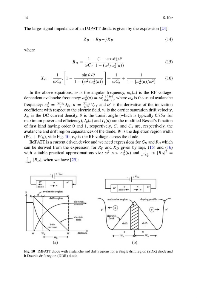
(W A + W D ), vide Fig. 10, v r.f is the RF voltage across the diode.
IMPATT is a current driven device and we need expressions for G D and B D which
can be derived from the expression for R D and X D given by Eqs. (15) and (16)
with suitable practical approximations viz.: ω
2
>> ω
2
a (u) and
1
ω 2 C
2
T
≈ |R D |
2
=
1
|G D | .|R D |, when we have [25]:
Fig. 10 IMPATT diode with avalanche and drift regions for a Single drift region (SDR) diode and
b Double drift region (DDR) diode
S. Kar
The large-signal impedance of an IMPATT diode is given by the expression [24]:
Z D = R D − j X D
(14)
where
R D =
1
ωC d
.
(1 − cos θ )/θ
1 −
ω 2 /ω 2
a (u)
(15)
X D =
1
ωC d
.
1 −
sin θ/θ
1 −
ω 2 /ω 2
a (u)
+
1
ωC a
+
1
1 −
ω 2
a (u)/ω 2
(16)
In the above equations, ω is the angular frequency, ω a (u) is the RF voltagedependent avalanche frequency: ω
2
a (u) = ω
2
a
2I 1 (u)
u.I 0 (u)
, where ω a is the usual avalanche
frequency: ω
2
a =
3α
v s
ε
J dc , u =
3α
v s
ωW
V r. f and α
is the derivative of the ionization
coefficient with respect to the electric field, v s is the carrier saturation drift velocity,
J dc is the DC current density, θ is the transit angle (which is typically 0.75π for
maximum power and efficiency), I 0 (u) and I 1 (u) are the modified Bessel’s function
of first kind having order 0 and 1, respectively, C a and C d are, respectively, the
avalanche and drift region capacitances of the diode, W is the depletion region width
(W A + W D ), vide Fig. 10, v r.f is the RF voltage across the diode.
IMPATT is a current driven device and we need expressions for G D and B D which
can be derived from the expression for R D and X D given by Eqs. (15) and (16)
with suitable practical approximations viz.: ω
2
>> ω
2
a (u) and
1
ω 2 C
2
T
≈ |R D |
2
=
1
|G D | .|R D |, when we have [25]:
Fig. 10 IMPATT diode with avalanche and drift regions for a Single drift region (SDR) diode and
b Double drift region (DDR) diode