

178
K. Mukherjee et al.
the first time since no literature is found in similar topic. These devices are analyzed
considering input/output bit patterns, on/off ratio and its dependence on control power
and amplified spontaneous emission noise (ASE). This chapter is divided as follows:
Section 2 deals with basic switching of TOAD, Sect. 3 mathematical modeling and
in subsequent sections sum, carry, and borrow generations are discussed. Operations
of half adder, half subtractor along with simulation results are given in Sects. 5, 6
and 7, respectively. Section 8 concludes the chapter.
2 Working Principle of TOAD
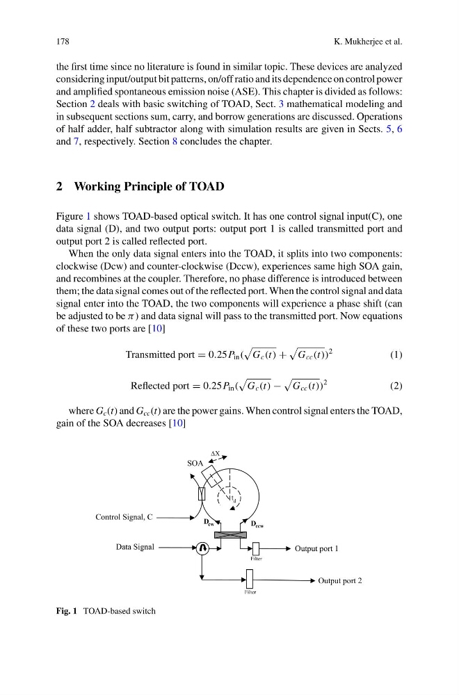
Figure 1 shows TOAD-based optical switch. It has one control signal input(C), one
data signal (D), and two output ports: output port 1 is called transmitted port and
output port 2 is called reflected port.
When the only data signal enters into the TOAD, it splits into two components:
clockwise (Dcw) and counter-clockwise (Dccw), experiences same high SOA gain,
and recombines at the coupler. Therefore, no phase difference is introduced between
them; the data signal comes out of the reflected port. When the control signal and data
signal enter into the TOAD, the two components will experience a phase shift (can
be adjusted to be π ) and data signal will pass to the transmitted port. Now equations
of these two ports are [10]
Transmitted port = 0.25P in (
G c (t) +
G cc (t))
2
(1)
Reflected port = 0.25P in (
G c (t) −
G cc (t))
2
(2)
where G c (t) and G cc (t) are the power gains. When control signal enters the TOAD,
gain of the SOA decreases [10]
t d
SOA
∆X
D ccw
D cw
Filter
Filter
Output port 1
Control Signal, C
Data Signal
Output port 2
Fig. 1 TOAD-based switch
K. Mukherjee et al.
the first time since no literature is found in similar topic. These devices are analyzed
considering input/output bit patterns, on/off ratio and its dependence on control power
and amplified spontaneous emission noise (ASE). This chapter is divided as follows:
Section 2 deals with basic switching of TOAD, Sect. 3 mathematical modeling and
in subsequent sections sum, carry, and borrow generations are discussed. Operations
of half adder, half subtractor along with simulation results are given in Sects. 5, 6
and 7, respectively. Section 8 concludes the chapter.
2 Working Principle of TOAD
Figure 1 shows TOAD-based optical switch. It has one control signal input(C), one
data signal (D), and two output ports: output port 1 is called transmitted port and
output port 2 is called reflected port.
When the only data signal enters into the TOAD, it splits into two components:
clockwise (Dcw) and counter-clockwise (Dccw), experiences same high SOA gain,
and recombines at the coupler. Therefore, no phase difference is introduced between
them; the data signal comes out of the reflected port. When the control signal and data
signal enter into the TOAD, the two components will experience a phase shift (can
be adjusted to be π ) and data signal will pass to the transmitted port. Now equations
of these two ports are [10]
Transmitted port = 0.25P in (
G c (t) +
G cc (t))
2
(1)
Reflected port = 0.25P in (
G c (t) −
G cc (t))
2
(2)
where G c (t) and G cc (t) are the power gains. When control signal enters the TOAD,
gain of the SOA decreases [10]
t d
SOA
∆X
D ccw
D cw
Filter
Filter
Output port 1
Control Signal, C
Data Signal
Output port 2
Fig. 1 TOAD-based switch