

4
S. Kar
an exponential taper transformer as shown in Fig. 2c. Another version of reducedheight waveguide is coaxial-waveguide configuration where the circuit impedance
is lowered by reduced-height waveguide followed by coaxial spacers, vide Fig. 2d.
Such an oscillator configuration is normally used at millimetre-wave frequency that
provides higher power and broad band operation [20]. But advantage with resonantcap circuit is that here the active device can be mounted in full-height waveguide
via the resonant-cap where the resonant-cap behaves as a quarter-wave transformer,
thereby ensuring the impedance matching between the device and the waveguide
circuit. Further, the resonant-cap cavity that primarily determines the oscillator characteristics has a very high Q value and hence provides reasonably good power output
even at millimetre-wave frequency. Thus for THz oscillator design, it is expected
that resonant-cap circuit will be a better choice for oscillator design.
The resonant-cap is a thin metal disc attached to a bias-post which is inserted
from the top broad wall of the waveguide (vide Fig. 2d). Lower face of the metal
disc of the resonant-cap structure and upper face of the bottom broad wall of the
waveguide forms the resonant-cap cavity that acts as a radial transmission line. Such
a cavity is bounded in the top and bottom by electric walls having open magnetic
walls on the sides of the cavity with E z and H ϕ as the existing field components with
signal propagation (i.e. k vector) along the radial direction of the disc. The oscillation
frequency in resonant-cap-type oscillator is primarily determined by the radius of
the disc which is approximately a quarter wavelengths. The resonant-cap cavity is a
very high Q cavity; thus, a resonant-cap-type oscillator is inherently a narrowband
oscillator.
Just as in lower frequency, broadband of operation can be realized by coupling two
resonant circuits, thereby forming a ‘skirt’ pattern resonant characteristic, a slotteddisc resonant-cap can do the same for microwave and millimetre-wave oscillator
[13]. For resonant-cap oscillator, it is known that: f 0 ·r = constant; where r is the
radius of the disc and f 0 is the resonant frequency of the oscillator determined by the
radius r of the disc of resonant-cap structure. Thus for slotted-disc resonant-cap, vide
Fig. 3, with f in > f out (f in and f out are determined respectively by the inner radius,
R i , and outer radius, R, of the slotted-disc structure); we can expect realization of
broadband for slotted-disc resonant-cap compared to un-slotted disc resonant-cap
structure.
With the help of an empirical formula, the effective resonant frequency of the
slotted-disc resonant-cap can be determined [13]. It will have two resonant frequencies f in and f out , the former being determined by the inner radius R i and latter by
the outer radius R (vide Fig. 3c). f in is due to the effectiveness of the inner circle of
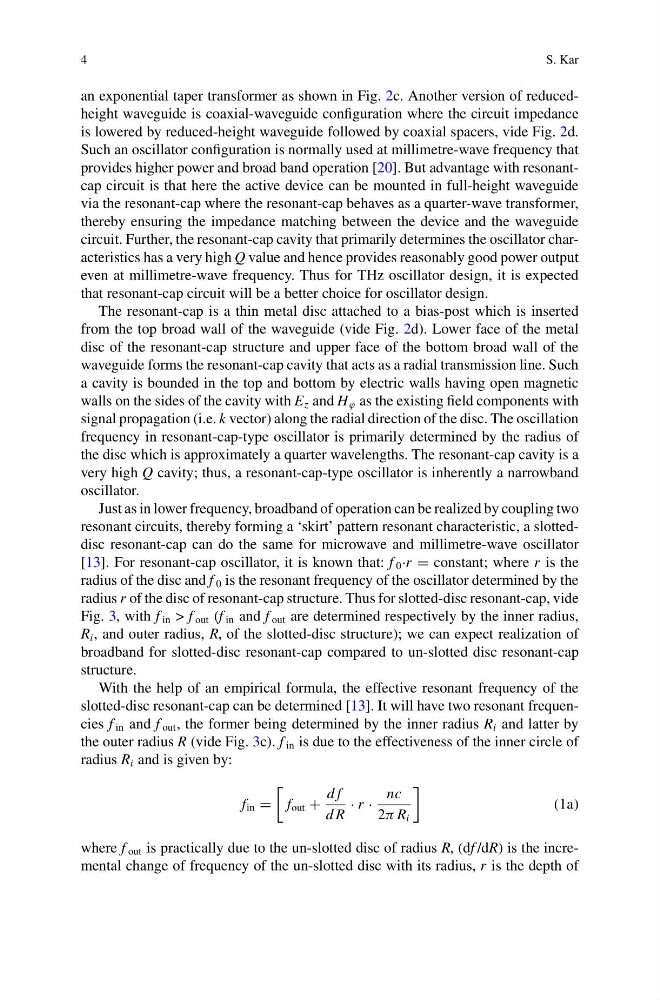
radius R i and is given by:
f in =
f out +
d f
d R
· r ·
nc
2π R i
(1a)
where f out is practically due to the un-slotted disc of radius R, (df /dR) is the incremental change of frequency of the un-slotted disc with its radius, r is the depth of
S. Kar
an exponential taper transformer as shown in Fig. 2c. Another version of reducedheight waveguide is coaxial-waveguide configuration where the circuit impedance
is lowered by reduced-height waveguide followed by coaxial spacers, vide Fig. 2d.
Such an oscillator configuration is normally used at millimetre-wave frequency that
provides higher power and broad band operation [20]. But advantage with resonantcap circuit is that here the active device can be mounted in full-height waveguide
via the resonant-cap where the resonant-cap behaves as a quarter-wave transformer,
thereby ensuring the impedance matching between the device and the waveguide
circuit. Further, the resonant-cap cavity that primarily determines the oscillator characteristics has a very high Q value and hence provides reasonably good power output
even at millimetre-wave frequency. Thus for THz oscillator design, it is expected
that resonant-cap circuit will be a better choice for oscillator design.
The resonant-cap is a thin metal disc attached to a bias-post which is inserted
from the top broad wall of the waveguide (vide Fig. 2d). Lower face of the metal
disc of the resonant-cap structure and upper face of the bottom broad wall of the
waveguide forms the resonant-cap cavity that acts as a radial transmission line. Such
a cavity is bounded in the top and bottom by electric walls having open magnetic
walls on the sides of the cavity with E z and H ϕ as the existing field components with
signal propagation (i.e. k vector) along the radial direction of the disc. The oscillation
frequency in resonant-cap-type oscillator is primarily determined by the radius of
the disc which is approximately a quarter wavelengths. The resonant-cap cavity is a
very high Q cavity; thus, a resonant-cap-type oscillator is inherently a narrowband
oscillator.
Just as in lower frequency, broadband of operation can be realized by coupling two
resonant circuits, thereby forming a ‘skirt’ pattern resonant characteristic, a slotteddisc resonant-cap can do the same for microwave and millimetre-wave oscillator
[13]. For resonant-cap oscillator, it is known that: f 0 ·r = constant; where r is the
radius of the disc and f 0 is the resonant frequency of the oscillator determined by the
radius r of the disc of resonant-cap structure. Thus for slotted-disc resonant-cap, vide
Fig. 3, with f in > f out (f in and f out are determined respectively by the inner radius,
R i , and outer radius, R, of the slotted-disc structure); we can expect realization of
broadband for slotted-disc resonant-cap compared to un-slotted disc resonant-cap
structure.
With the help of an empirical formula, the effective resonant frequency of the
slotted-disc resonant-cap can be determined [13]. It will have two resonant frequencies f in and f out , the former being determined by the inner radius R i and latter by
the outer radius R (vide Fig. 3c). f in is due to the effectiveness of the inner circle of
radius R i and is given by:
f in =
f out +
d f
d R
· r ·
nc
2π R i
(1a)
where f out is practically due to the un-slotted disc of radius R, (df /dR) is the incremental change of frequency of the un-slotted disc with its radius, r is the depth of