

10 Realization of Artificial Chirality in Micro-/Nano-Scale …
253
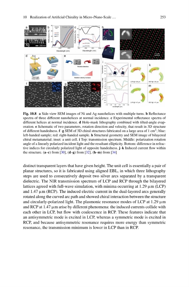
Fig. 10.8 a Side-view SEM images of Ni and Ag nanohelices with multiple turns. b Reflectance
spectra of three different nanohelices at normal incidence. c Experimental reflectance spectra of
different helices at normal incidence. d Hole-mask lithography combined with tilted-angle evaporation. e Schematic of two parameters, rotation direction and velocity, that result in 3D structure
of different handedness. f–g SEM of 3D chiral structures fabricated on a large area of 1 cm 2 ; blue:
left-handed sample; red: right-handed sample. h Structural geometry and SEM image of bilayered
chiral metamaterial; inset: a unit cell. i Top: transmission spectrum. Middle: polarization rotation
angle of a linearly polarized incident light and the resultant ellipticity. Bottom: difference in refractive indices for circularly polarized light of opposite handedness. j–k Induced current flow within
the structure. (a–c) from [30], (d–g) from [32], (h–m) from [34]
distinct transparent layers that have given height. The unit cell is essentially a pair of
planar structures, so it is fabricated using aligned EBL, in which three lithography
steps are used to consecutively deposit two silver arcs separated by a transparent
dielectric. The NIR transmission spectrum of LCP and RCP through the bilayered
lattices agreed with full-wave simulation, with minima occurring at 1.29 μm (LCP)
and 1.47 μm (RCP). The induced electric current in the dual-layered arcs generally
rotated along the curved arc path and showed chiral interaction between the structure
and circularly-polarized light. The plasmonic resonance modes of LCP at 1.29 μm
and RCP at 1.47 μm arise by different phenomena: the induced currents collide with
each other in LCP, but flow with coalescence in RCP. These features indicate that
an antisymmetric mode is excited in LCP, whereas a symmetric mode is excited in
RCP, and because antisymmetric resonance requires more energy than symmetric
resonance, the transmission minimum is lower in LCP than in RCP.
253
Fig. 10.8 a Side-view SEM images of Ni and Ag nanohelices with multiple turns. b Reflectance
spectra of three different nanohelices at normal incidence. c Experimental reflectance spectra of
different helices at normal incidence. d Hole-mask lithography combined with tilted-angle evaporation. e Schematic of two parameters, rotation direction and velocity, that result in 3D structure
of different handedness. f–g SEM of 3D chiral structures fabricated on a large area of 1 cm 2 ; blue:
left-handed sample; red: right-handed sample. h Structural geometry and SEM image of bilayered
chiral metamaterial; inset: a unit cell. i Top: transmission spectrum. Middle: polarization rotation
angle of a linearly polarized incident light and the resultant ellipticity. Bottom: difference in refractive indices for circularly polarized light of opposite handedness. j–k Induced current flow within
the structure. (a–c) from [30], (d–g) from [32], (h–m) from [34]
distinct transparent layers that have given height. The unit cell is essentially a pair of
planar structures, so it is fabricated using aligned EBL, in which three lithography
steps are used to consecutively deposit two silver arcs separated by a transparent
dielectric. The NIR transmission spectrum of LCP and RCP through the bilayered
lattices agreed with full-wave simulation, with minima occurring at 1.29 μm (LCP)
and 1.47 μm (RCP). The induced electric current in the dual-layered arcs generally
rotated along the curved arc path and showed chiral interaction between the structure
and circularly-polarized light. The plasmonic resonance modes of LCP at 1.29 μm
and RCP at 1.47 μm arise by different phenomena: the induced currents collide with
each other in LCP, but flow with coalescence in RCP. These features indicate that
an antisymmetric mode is excited in LCP, whereas a symmetric mode is excited in
RCP, and because antisymmetric resonance requires more energy than symmetric
resonance, the transmission minimum is lower in LCP than in RCP.