

386
M. Hattab et al.
b
a
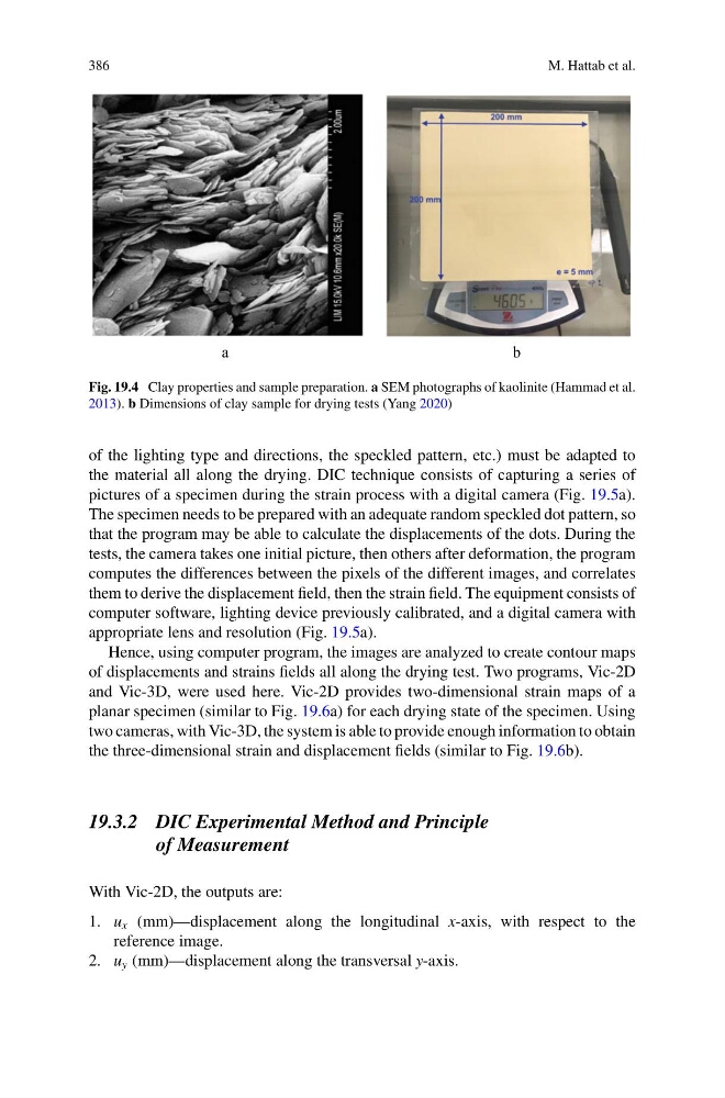
Fig. 19.4 Clay properties and sample preparation. a SEM photographs of kaolinite (Hammad et al.
2013). b Dimensions of clay sample for drying tests (Yang 2020)
of the lighting type and directions, the speckled pattern, etc.) must be adapted to
the material all along the drying. DIC technique consists of capturing a series of
pictures of a specimen during the strain process with a digital camera (Fig. 19.5a).
The specimen needs to be prepared with an adequate random speckled dot pattern, so
that the program may be able to calculate the displacements of the dots. During the
tests, the camera takes one initial picture, then others after deformation, the program
computes the differences between the pixels of the different images, and correlates
them to derive the displacement field, then the strain field. The equipment consists of
computer software, lighting device previously calibrated, and a digital camera with
appropriate lens and resolution (Fig. 19.5a).
Hence, using computer program, the images are analyzed to create contour maps
of displacements and strains fields all along the drying test. Two programs, Vic-2D
and Vic-3D, were used here. Vic-2D provides two-dimensional strain maps of a
planar specimen (similar to Fig. 19.6a) for each drying state of the specimen. Using
two cameras, with Vic-3D, the system is able to provide enough information to obtain
the three-dimensional strain and displacement fields (similar to Fig. 19.6b).
19.3.2 DIC Experimental Method and Principle
of Measurement
With Vic-2D, the outputs are:
1. u x (mm)—displacement along the longitudinal x-axis, with respect to the
reference image.
2. u y (mm)—displacement along the transversal y-axis.
M. Hattab et al.
b
a
Fig. 19.4 Clay properties and sample preparation. a SEM photographs of kaolinite (Hammad et al.
2013). b Dimensions of clay sample for drying tests (Yang 2020)
of the lighting type and directions, the speckled pattern, etc.) must be adapted to
the material all along the drying. DIC technique consists of capturing a series of
pictures of a specimen during the strain process with a digital camera (Fig. 19.5a).
The specimen needs to be prepared with an adequate random speckled dot pattern, so
that the program may be able to calculate the displacements of the dots. During the
tests, the camera takes one initial picture, then others after deformation, the program
computes the differences between the pixels of the different images, and correlates
them to derive the displacement field, then the strain field. The equipment consists of
computer software, lighting device previously calibrated, and a digital camera with
appropriate lens and resolution (Fig. 19.5a).
Hence, using computer program, the images are analyzed to create contour maps
of displacements and strains fields all along the drying test. Two programs, Vic-2D
and Vic-3D, were used here. Vic-2D provides two-dimensional strain maps of a
planar specimen (similar to Fig. 19.6a) for each drying state of the specimen. Using
two cameras, with Vic-3D, the system is able to provide enough information to obtain
the three-dimensional strain and displacement fields (similar to Fig. 19.6b).
19.3.2 DIC Experimental Method and Principle
of Measurement
With Vic-2D, the outputs are:
1. u x (mm)—displacement along the longitudinal x-axis, with respect to the
reference image.
2. u y (mm)—displacement along the transversal y-axis.