

82
5 Erosion and Deposition and Their Influence on Plasma …
Louvers in front
of cryo-pump
(No image)
Plasma shadow area
Heavily deposited
\
\
\
JET Mark-IIA divertor
Deposition on plasma facing surface
caused by tile alignment
BN1
BN2
BN3
BN4
BN5
BN6
BN7
BN10
BN9
BN8
Tritium intensity
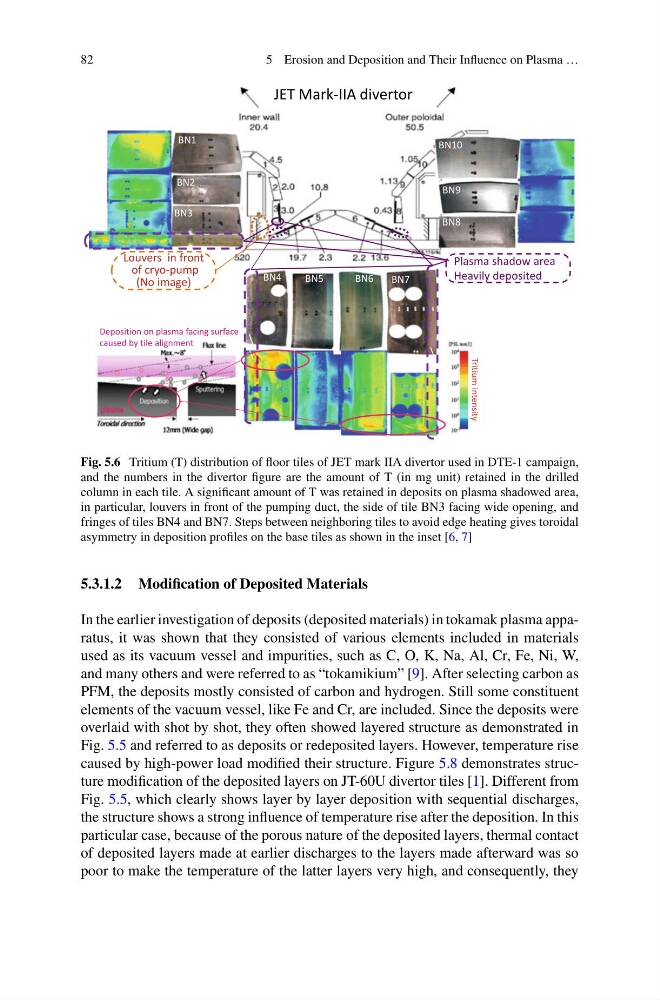
Fig. 5.6 Tritium (T) distribution of floor tiles of JET mark IIA divertor used in DTE-1 campaign,
and the numbers in the divertor figure are the amount of T (in mg unit) retained in the drilled
column in each tile. A significant amount of T was retained in deposits on plasma shadowed area,
in particular, louvers in front of the pumping duct, the side of tile BN3 facing wide opening, and
fringes of tiles BN4 and BN7. Steps between neighboring tiles to avoid edge heating gives toroidal
asymmetry in deposition profiles on the base tiles as shown in the inset [6, 7]
5.3.1.2 Modification of Deposited Materials
In the earlier investigation of deposits (deposited materials) in tokamak plasma apparatus, it was shown that they consisted of various elements included in materials
used as its vacuum vessel and impurities, such as C, O, K, Na, Al, Cr, Fe, Ni, W,
and many others and were referred to as “tokamikium” [9]. After selecting carbon as
PFM, the deposits mostly consisted of carbon and hydrogen. Still some constituent
elements of the vacuum vessel, like Fe and Cr, are included. Since the deposits were
overlaid with shot by shot, they often showed layered structure as demonstrated in
Fig. 5.5 and referred to as deposits or redeposited layers. However, temperature rise
caused by high-power load modified their structure. Figure 5.8 demonstrates structure modification of the deposited layers on JT-60U divertor tiles [1]. Different from
Fig. 5.5, which clearly shows layer by layer deposition with sequential discharges,
the structure shows a strong influence of temperature rise after the deposition. In this
particular case, because of the porous nature of the deposited layers, thermal contact
of deposited layers made at earlier discharges to the layers made afterward was so
poor to make the temperature of the latter layers very high, and consequently, they
5 Erosion and Deposition and Their Influence on Plasma …
Louvers in front
of cryo-pump
(No image)
Plasma shadow area
Heavily deposited
\
\
\
JET Mark-IIA divertor
Deposition on plasma facing surface
caused by tile alignment
BN1
BN2
BN3
BN4
BN5
BN6
BN7
BN10
BN9
BN8
Tritium intensity
Fig. 5.6 Tritium (T) distribution of floor tiles of JET mark IIA divertor used in DTE-1 campaign,
and the numbers in the divertor figure are the amount of T (in mg unit) retained in the drilled
column in each tile. A significant amount of T was retained in deposits on plasma shadowed area,
in particular, louvers in front of the pumping duct, the side of tile BN3 facing wide opening, and
fringes of tiles BN4 and BN7. Steps between neighboring tiles to avoid edge heating gives toroidal
asymmetry in deposition profiles on the base tiles as shown in the inset [6, 7]
5.3.1.2 Modification of Deposited Materials
In the earlier investigation of deposits (deposited materials) in tokamak plasma apparatus, it was shown that they consisted of various elements included in materials
used as its vacuum vessel and impurities, such as C, O, K, Na, Al, Cr, Fe, Ni, W,
and many others and were referred to as “tokamikium” [9]. After selecting carbon as
PFM, the deposits mostly consisted of carbon and hydrogen. Still some constituent
elements of the vacuum vessel, like Fe and Cr, are included. Since the deposits were
overlaid with shot by shot, they often showed layered structure as demonstrated in
Fig. 5.5 and referred to as deposits or redeposited layers. However, temperature rise
caused by high-power load modified their structure. Figure 5.8 demonstrates structure modification of the deposited layers on JT-60U divertor tiles [1]. Different from
Fig. 5.5, which clearly shows layer by layer deposition with sequential discharges,
the structure shows a strong influence of temperature rise after the deposition. In this
particular case, because of the porous nature of the deposited layers, thermal contact
of deposited layers made at earlier discharges to the layers made afterward was so
poor to make the temperature of the latter layers very high, and consequently, they