

3.2 Estimation of Power Load and Its Distribution in a Fusion Reactor
39
Fusion Power
3 Gwth Neutron load
External heating
50 MW
α heating
Heat exhaust
650MW
2.4 GW
=> 2.4 MW/m 2 (av.)
Divertor
Core radiation
Edge cooling
Particle load
500MW
=> 0.5 MW/m 2 (av.)
150MW
=> 1 - 2 MW/m 2
(First wall)
=> 10 - 20 MW/m 2
(Divetor plate)
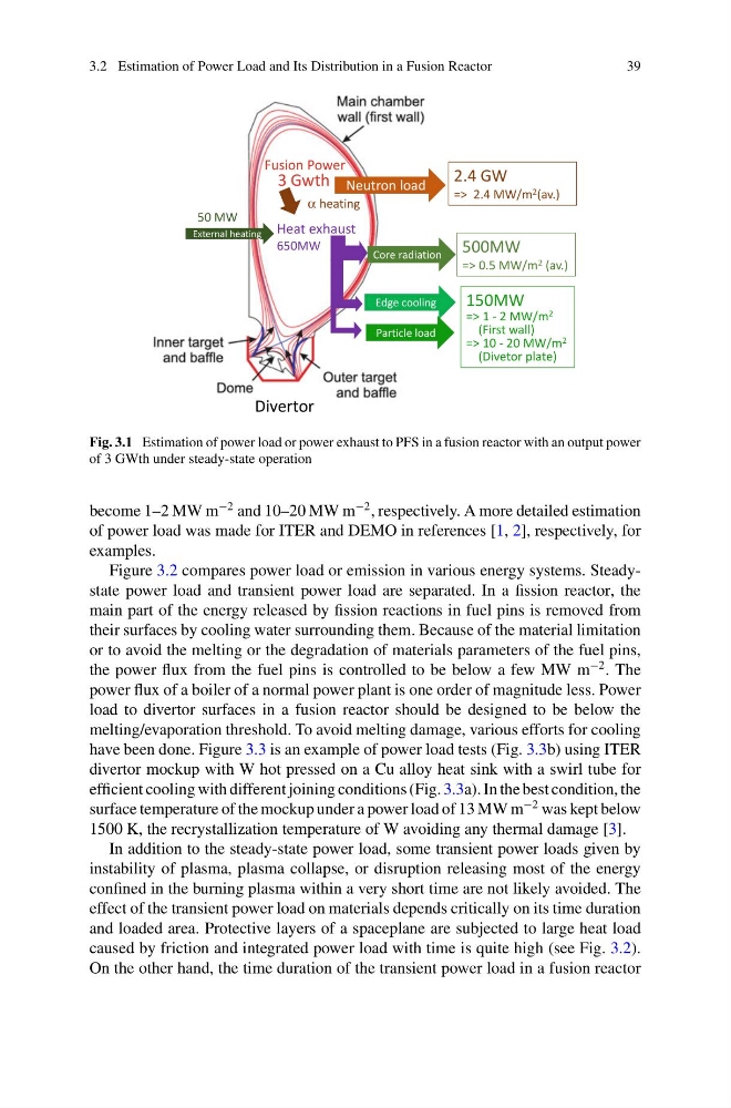
Fig. 3.1 Estimation of power load or power exhaust to PFS in a fusion reactor with an output power
of 3 GWth under steady-state operation
become 1–2 MW m
−2 and 10–20 MW m
−2 , respectively. A more detailed estimation
of power load was made for ITER and DEMO in references [1, 2], respectively, for
examples.
Figure 3.2 compares power load or emission in various energy systems. Steadystate power load and transient power load are separated. In a fission reactor, the
main part of the energy released by fission reactions in fuel pins is removed from
their surfaces by cooling water surrounding them. Because of the material limitation
or to avoid the melting or the degradation of materials parameters of the fuel pins,
the power flux from the fuel pins is controlled to be below a few MW m
−2 . The
power flux of a boiler of a normal power plant is one order of magnitude less. Power
load to divertor surfaces in a fusion reactor should be designed to be below the
melting/evaporation threshold. To avoid melting damage, various efforts for cooling
have been done. Figure 3.3 is an example of power load tests (Fig. 3.3b) using ITER
divertor mockup with W hot pressed on a Cu alloy heat sink with a swirl tube for
efficient cooling with different joining conditions (Fig. 3.3a). In the best condition, the
surface temperature of the mockup under a power load of 13 MW m
−2 was kept below
1500 K, the recrystallization temperature of W avoiding any thermal damage [3].
In addition to the steady-state power load, some transient power loads given by
instability of plasma, plasma collapse, or disruption releasing most of the energy
confined in the burning plasma within a very short time are not likely avoided. The
effect of the transient power load on materials depends critically on its time duration
and loaded area. Protective layers of a spaceplane are subjected to large heat load
caused by friction and integrated power load with time is quite high (see Fig. 3.2).
On the other hand, the time duration of the transient power load in a fusion reactor
39
Fusion Power
3 Gwth Neutron load
External heating
50 MW
α heating
Heat exhaust
650MW
2.4 GW
=> 2.4 MW/m 2 (av.)
Divertor
Core radiation
Edge cooling
Particle load
500MW
=> 0.5 MW/m 2 (av.)
150MW
=> 1 - 2 MW/m 2
(First wall)
=> 10 - 20 MW/m 2
(Divetor plate)
Fig. 3.1 Estimation of power load or power exhaust to PFS in a fusion reactor with an output power
of 3 GWth under steady-state operation
become 1–2 MW m
−2 and 10–20 MW m
−2 , respectively. A more detailed estimation
of power load was made for ITER and DEMO in references [1, 2], respectively, for
examples.
Figure 3.2 compares power load or emission in various energy systems. Steadystate power load and transient power load are separated. In a fission reactor, the
main part of the energy released by fission reactions in fuel pins is removed from
their surfaces by cooling water surrounding them. Because of the material limitation
or to avoid the melting or the degradation of materials parameters of the fuel pins,
the power flux from the fuel pins is controlled to be below a few MW m
−2 . The
power flux of a boiler of a normal power plant is one order of magnitude less. Power
load to divertor surfaces in a fusion reactor should be designed to be below the
melting/evaporation threshold. To avoid melting damage, various efforts for cooling
have been done. Figure 3.3 is an example of power load tests (Fig. 3.3b) using ITER
divertor mockup with W hot pressed on a Cu alloy heat sink with a swirl tube for
efficient cooling with different joining conditions (Fig. 3.3a). In the best condition, the
surface temperature of the mockup under a power load of 13 MW m
−2 was kept below
1500 K, the recrystallization temperature of W avoiding any thermal damage [3].
In addition to the steady-state power load, some transient power loads given by
instability of plasma, plasma collapse, or disruption releasing most of the energy
confined in the burning plasma within a very short time are not likely avoided. The
effect of the transient power load on materials depends critically on its time duration
and loaded area. Protective layers of a spaceplane are subjected to large heat load
caused by friction and integrated power load with time is quite high (see Fig. 3.2).
On the other hand, the time duration of the transient power load in a fusion reactor