

116
7 Fundamentals of Hydrogen Recycling
understanding of hydrogen recycling in tokamaks and those given by laboratory
experiments. Fundamentals of hydrogen interactions with fusion reactor materials
are written in a textbook [2].
7.2 Overall Fuel Flow at Steady-State Burning
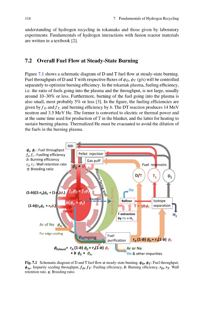
Figure 7.1 shows a schematic diagram of D and T fuel flow at steady-state burning.
Fuel throughputs of D and T with respective fluxes of φ D , φ T (g/s) will be controlled
separately to optimize burning efficiency. In the tokamak plasma, fueling efficiency,
i.e. the ratio of fuels going into the plasma and the throughput, is not large, usually
around 10–30% or less. Furthermore, burning of the fuel going into the plasma is
also small, most probably 5% or less [3]. In the figure, the fueling efficiencies are
given by f D and f T, and burning efficiency by b. The DT reaction produces 14 MeV
neutron and 3.5 MeV He. The former is converted to electric or thermal power and
at the same time used for production of T in the blanket, and the latter for heating to
sustain burning plasma. Thermalized He must be evacuated to avoid the dilution of
the fuels in the burning plasma.
Fig. 7.1 Schematic diagram of D and T fuel flow at steady-state burning. φ D , φ T : Fuel throughput,
φ Ar: Impurity seeding throughput, f D , f T : Fueling efficiency, b: Burning efficiency, r D , r T: Wall
retention rate, η: Breeding ratio
7 Fundamentals of Hydrogen Recycling
understanding of hydrogen recycling in tokamaks and those given by laboratory
experiments. Fundamentals of hydrogen interactions with fusion reactor materials
are written in a textbook [2].
7.2 Overall Fuel Flow at Steady-State Burning
Figure 7.1 shows a schematic diagram of D and T fuel flow at steady-state burning.
Fuel throughputs of D and T with respective fluxes of φ D , φ T (g/s) will be controlled
separately to optimize burning efficiency. In the tokamak plasma, fueling efficiency,
i.e. the ratio of fuels going into the plasma and the throughput, is not large, usually
around 10–30% or less. Furthermore, burning of the fuel going into the plasma is
also small, most probably 5% or less [3]. In the figure, the fueling efficiencies are
given by f D and f T, and burning efficiency by b. The DT reaction produces 14 MeV
neutron and 3.5 MeV He. The former is converted to electric or thermal power and
at the same time used for production of T in the blanket, and the latter for heating to
sustain burning plasma. Thermalized He must be evacuated to avoid the dilution of
the fuels in the burning plasma.
Fig. 7.1 Schematic diagram of D and T fuel flow at steady-state burning. φ D , φ T : Fuel throughput,
φ Ar: Impurity seeding throughput, f D , f T : Fueling efficiency, b: Burning efficiency, r D , r T: Wall
retention rate, η: Breeding ratio