

362
5 X-ray Pulsar-Based Navigation: Theories and Experiments
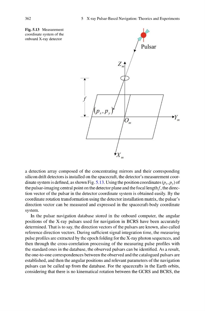
Fig. 5.13 Measurement
coordinate system of the
onboard X-ray detector
a detection array composed of the concentrating mirrors and their corresponding
silicon drift detectors is installed on the spacecraft, the detector’s measurement coordinate system is defined, as shown Fig. 5.13. Using the position coordinates (p x , p y ) of
the pulsar-imaging central point on the detector plane and the focal length f , the direction vector of the pulsar in the detector coordinate system is obtained easily. By the
coordinate rotation transformation using the detector installation matrix, the pulsar’s
direction vector can be measured and expressed in the spacecraft-body coordinate
system.
In the pulsar navigation database stored in the onboard computer, the angular
positions of the X-ray pulsars used for navigation in BCRS have been accurately
determined. That is to say, the direction vectors of the pulsars are known, also called
reference direction vectors. During sufficient signal integration time, the measuring
pulse profiles are extracted by the epoch folding for the X-ray photon sequences, and
then through the cross-correlation processing of the measuring pulse profiles with
the standard ones in the database, the observed pulsars can be identified. As a result,
the one-to-one correspondences between the observed and the catalogued pulsars are
established, and then the angular positions and relevant parameters of the navigation
pulsars can be called up from the database. For the spacecrafts in the Earth orbits,
considering that there is no kinematical rotation between the GCRS and BCRS, the
5 X-ray Pulsar-Based Navigation: Theories and Experiments
Fig. 5.13 Measurement
coordinate system of the
onboard X-ray detector
a detection array composed of the concentrating mirrors and their corresponding
silicon drift detectors is installed on the spacecraft, the detector’s measurement coordinate system is defined, as shown Fig. 5.13. Using the position coordinates (p x , p y ) of
the pulsar-imaging central point on the detector plane and the focal length f , the direction vector of the pulsar in the detector coordinate system is obtained easily. By the
coordinate rotation transformation using the detector installation matrix, the pulsar’s
direction vector can be measured and expressed in the spacecraft-body coordinate
system.
In the pulsar navigation database stored in the onboard computer, the angular
positions of the X-ray pulsars used for navigation in BCRS have been accurately
determined. That is to say, the direction vectors of the pulsars are known, also called
reference direction vectors. During sufficient signal integration time, the measuring
pulse profiles are extracted by the epoch folding for the X-ray photon sequences, and
then through the cross-correlation processing of the measuring pulse profiles with
the standard ones in the database, the observed pulsars can be identified. As a result,
the one-to-one correspondences between the observed and the catalogued pulsars are
established, and then the angular positions and relevant parameters of the navigation
pulsars can be called up from the database. For the spacecrafts in the Earth orbits,
considering that there is no kinematical rotation between the GCRS and BCRS, the