

E1C12 09/14/2010
13:54:20 Page 561
12.19 Pneumatic actuators span a very large range of size and force. Research the range of commercially
available pneumatic cylinders.
12.20 Estimate the flow coefficient for a flow control valve if the rating corresponds to 32 SCFM (0.906
SCMM) with a Dp ¼ 10 psi (0.69 bar). The test is conducted using air with a line pressure of 100 psi
(6.7 bar), T ¼ 68
F (20
C), and a relative humidity of 36% at the supply port. What is the pressure at
the exhaust port? Base your answer on standard conditions.
12.21 A low profile three-port control valve with 6-mm port diameters has an F value of 0.82 ms/cc and a
lag time of 8 ms to pressurize through ports P to A. The exhaust path through ports T to A has an F
value of 0.70 ms/cc with an 8 ms lag time. The valve is connected to a 500 mL vessel. Supply
pressure is 1 bar; exhaust pressure is 0 bar. Estimate the time needed to pressurize this vessel to 0.9
bar. Estimate the time to exhaust this vessel to 0.1 bar.
12.22 Research the design of a totalizing flow meter, with particular emphasis on the meters used to
generate water bills.
12.23 The companion software includes a program stroboscope.vi that models the behavior of a stroboscope.
a. Set the bar rotation frequency to 40 rps, and then set the strobe frequency to 20 and 40 Hz. Explain
your results.
b. Set the bar rotation frequency to 100 rps. Using f 1 ¼ 50 Hz and f N ¼ 10 Hz, apply Equation 12.15
to show that we can measure rotation frequencies larger than the maximum frequency of the
stroboscope. Be careful to find all N of the synchronous frequencies.
12.24 Describe the operating principle of a thermostat for residential applications, and the design of a
bimetallic sensor for measuring the temperature. How is a dead-band created in such an instrument?
12.25 Show that a proportional controller has a steady-state error. How would you quantify the steadystate error for a controller and a first-order system?
12.26 Using First order PID.vi, develop a model of the oven described in Example 12.5 coupled with a PI
controller. Vary the proportional and integral gains and discuss the resulting behavior of this firstorder system.
12.27 Using Second order PID.vi, develop a model for PID control of the oven described in Example 12.5. Vary
the gains and discuss the resulting behavior of the system. Quantify the power input required to achieve a
given response.
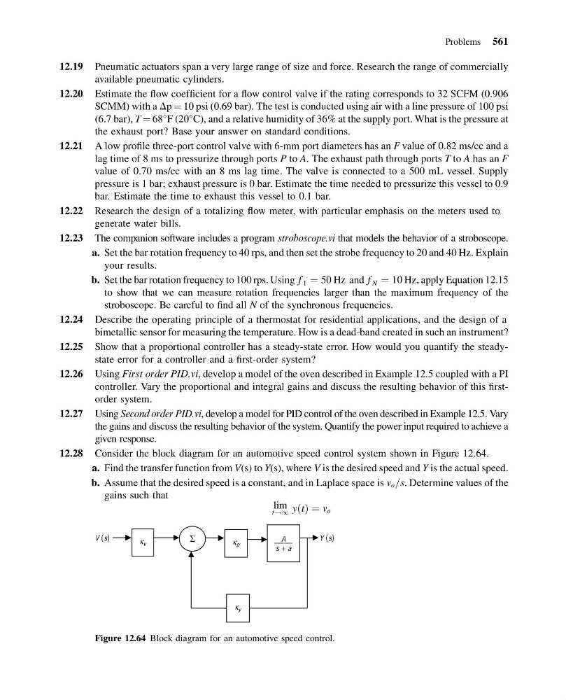
12.28 Consider the block diagram for an automotive speed control system shown in Figure 12.64.
a. Find the transfer function from V(s) to Y(s), where V is the desired speed and Y is the actual speed.
b. Assume that the desired speed is a constant, and in Laplace space is v o =s. Determine values of the
gains such that
t!1
lim yðtÞ ¼ v o
V (s)
∑
A
s + a
Y (s)
κ v
κ p
κ y
Figure 12.64 Block diagram for an automotive speed control.
Problems 561
13:54:20 Page 561
12.19 Pneumatic actuators span a very large range of size and force. Research the range of commercially
available pneumatic cylinders.
12.20 Estimate the flow coefficient for a flow control valve if the rating corresponds to 32 SCFM (0.906
SCMM) with a Dp ¼ 10 psi (0.69 bar). The test is conducted using air with a line pressure of 100 psi
(6.7 bar), T ¼ 68
F (20
C), and a relative humidity of 36% at the supply port. What is the pressure at
the exhaust port? Base your answer on standard conditions.
12.21 A low profile three-port control valve with 6-mm port diameters has an F value of 0.82 ms/cc and a
lag time of 8 ms to pressurize through ports P to A. The exhaust path through ports T to A has an F
value of 0.70 ms/cc with an 8 ms lag time. The valve is connected to a 500 mL vessel. Supply
pressure is 1 bar; exhaust pressure is 0 bar. Estimate the time needed to pressurize this vessel to 0.9
bar. Estimate the time to exhaust this vessel to 0.1 bar.
12.22 Research the design of a totalizing flow meter, with particular emphasis on the meters used to
generate water bills.
12.23 The companion software includes a program stroboscope.vi that models the behavior of a stroboscope.
a. Set the bar rotation frequency to 40 rps, and then set the strobe frequency to 20 and 40 Hz. Explain
your results.
b. Set the bar rotation frequency to 100 rps. Using f 1 ¼ 50 Hz and f N ¼ 10 Hz, apply Equation 12.15
to show that we can measure rotation frequencies larger than the maximum frequency of the
stroboscope. Be careful to find all N of the synchronous frequencies.
12.24 Describe the operating principle of a thermostat for residential applications, and the design of a
bimetallic sensor for measuring the temperature. How is a dead-band created in such an instrument?
12.25 Show that a proportional controller has a steady-state error. How would you quantify the steadystate error for a controller and a first-order system?
12.26 Using First order PID.vi, develop a model of the oven described in Example 12.5 coupled with a PI
controller. Vary the proportional and integral gains and discuss the resulting behavior of this firstorder system.
12.27 Using Second order PID.vi, develop a model for PID control of the oven described in Example 12.5. Vary
the gains and discuss the resulting behavior of the system. Quantify the power input required to achieve a
given response.
12.28 Consider the block diagram for an automotive speed control system shown in Figure 12.64.
a. Find the transfer function from V(s) to Y(s), where V is the desired speed and Y is the actual speed.
b. Assume that the desired speed is a constant, and in Laplace space is v o =s. Determine values of the
gains such that
t!1
lim yðtÞ ¼ v o
V (s)
∑
A
s + a
Y (s)
κ v
κ p
κ y
Figure 12.64 Block diagram for an automotive speed control.
Problems 561