

E1C12 09/14/2010
13:54:12 Page 535
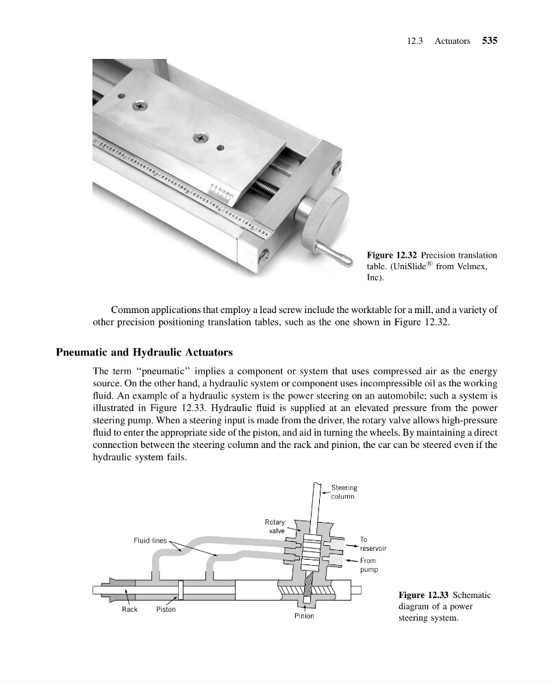
Common applications that employ a lead screw include the worktable for a mill, and a variety of
other precision positioning translation tables, such as the one shown in Figure 12.32.
Pneumatic and Hydraulic Actuators
The term ‘‘pneumatic’’ implies a component or system that uses compressed air as the energy
source. On the other hand, a hydraulic system or component uses incompressible oil as the working
fluid. An example of a hydraulic system is the power steering on an automobile; such a system is
illustrated in Figure 12.33. Hydraulic fluid is supplied at an elevated pressure from the power
steering pump. When a steering input is made from the driver, the rotary valve allows high-pressure
fluid to enter the appropriate side of the piston, and aid in turning the wheels. By maintaining a direct
connection between the steering column and the rack and pinion, the car can be steered even if the
hydraulic system fails.
Figure 12.32 Precision translation
table. (UniSlide
1 from Velmex,
Inc).
Pinion
Steering
column
To
reservoir
From
pump
Rotary
valve
Fluid lines
Rack
Piston
Figure 12.33 Schematic
diagram of a power
steering system.
12.3 Actuators 535
13:54:12 Page 535
Common applications that employ a lead screw include the worktable for a mill, and a variety of
other precision positioning translation tables, such as the one shown in Figure 12.32.
Pneumatic and Hydraulic Actuators
The term ‘‘pneumatic’’ implies a component or system that uses compressed air as the energy
source. On the other hand, a hydraulic system or component uses incompressible oil as the working
fluid. An example of a hydraulic system is the power steering on an automobile; such a system is
illustrated in Figure 12.33. Hydraulic fluid is supplied at an elevated pressure from the power
steering pump. When a steering input is made from the driver, the rotary valve allows high-pressure
fluid to enter the appropriate side of the piston, and aid in turning the wheels. By maintaining a direct
connection between the steering column and the rack and pinion, the car can be steered even if the
hydraulic system fails.
Figure 12.32 Precision translation
table. (UniSlide
1 from Velmex,
Inc).
Pinion
Steering
column
To
reservoir
From
pump
Rotary
valve
Fluid lines
Rack
Piston
Figure 12.33 Schematic
diagram of a power
steering system.
12.3 Actuators 535