

E1C12 09/14/2010
13:54:11 Page 524
rate can be decreased until another single synchronous image appears. If this flashing rate
corresponds to one-half the original rate, then the original rate is the actual speed. If it does not
occur at one-half the original value, then the original value is a submultiple.
The upper limit of the flash rate of the strobe does not limit the ability of the stroboscope to
measure rotational speed. For high speeds, synchronization can be achieved N times, with v 1
representing the maximum achievable synchronization speed, and v 2 ; v 3 ; . . . representing successively lower synchronization speeds. The measured rotational speed is then calculated as
v ¼
v 1 v N N À 1
ð
Þ
v 1 À v N
ð12:15Þ
The program file stroboscope.vi on the companion software disk illustrates the basic operation
and interesting stroboscopic effects.
Electromagnetic Techniques
Several measurement techniques for rotational velocity utilize transducers that generate electrical
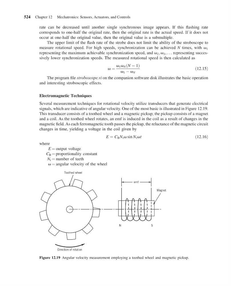
signals, which are indicative of angular velocity. One of the most basic is illustrated in Figure 12.19.
This transducer consists of a toothed wheel and a magnetic pickup; the pickup consists of a magnet
and a coil. As the toothed wheel rotates, an emf is induced in the coil as a result of changes in the
magnetic field. As each ferromagnetic tooth passes the pickup, the reluctance of the magnetic circuit
changes in time, yielding a voltage in the coil given by
E ¼ C B N t v sin N t vt
ð12:16Þ
where
E ¼ output voltage
C B ¼ proportionality constant
N t ¼ number of teeth
v ¼ angular velocity of the wheel
Toothed wheel
emf
N
S
Magnet
Direction of rotation
Figure 12.19 Angular velocity measurement employing a toothed wheel and magnetic pickup.
524 Chapter 12 Mechatronics: Sensors, Actuators, and Controls
13:54:11 Page 524
rate can be decreased until another single synchronous image appears. If this flashing rate
corresponds to one-half the original rate, then the original rate is the actual speed. If it does not
occur at one-half the original value, then the original value is a submultiple.
The upper limit of the flash rate of the strobe does not limit the ability of the stroboscope to
measure rotational speed. For high speeds, synchronization can be achieved N times, with v 1
representing the maximum achievable synchronization speed, and v 2 ; v 3 ; . . . representing successively lower synchronization speeds. The measured rotational speed is then calculated as
v ¼
v 1 v N N À 1
ð
Þ
v 1 À v N
ð12:15Þ
The program file stroboscope.vi on the companion software disk illustrates the basic operation
and interesting stroboscopic effects.
Electromagnetic Techniques
Several measurement techniques for rotational velocity utilize transducers that generate electrical
signals, which are indicative of angular velocity. One of the most basic is illustrated in Figure 12.19.
This transducer consists of a toothed wheel and a magnetic pickup; the pickup consists of a magnet
and a coil. As the toothed wheel rotates, an emf is induced in the coil as a result of changes in the
magnetic field. As each ferromagnetic tooth passes the pickup, the reluctance of the magnetic circuit
changes in time, yielding a voltage in the coil given by
E ¼ C B N t v sin N t vt
ð12:16Þ
where
E ¼ output voltage
C B ¼ proportionality constant
N t ¼ number of teeth
v ¼ angular velocity of the wheel
Toothed wheel
emf
N
S
Magnet
Direction of rotation
Figure 12.19 Angular velocity measurement employing a toothed wheel and magnetic pickup.
524 Chapter 12 Mechatronics: Sensors, Actuators, and Controls