

E1C12 09/14/2010
13:54:10 Page 522
typical. Moving coil transducers find application in seismic measurements as well as in vibration
applications.
Angular Velocity Measurements
The measurement of angular velocity finds a wide range of applications, including such familiar examples
as speedometers on automobiles. We consider a variety of applications and measurement techniques.
Mechanical Measurement Techniques
Mechanical means of measuring angular velocity or rotational speed were developed primarily to
provide feedback for control of engines and steam turbines. Mechanical governors and centrifugal
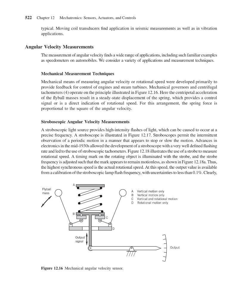
tachometers (4) operate on the principle illustrated in Figure 12.16. Here the centripetal acceleration
of the flyball masses result in a steady-state displacement of the spring, which provides a control
signal or is a direct indication of rotational speed. For this arrangement, the spring force is
proportional to the square of the angular velocity.
Stroboscopic Angular Velocity Measurements
A stroboscopic light source provides high-intensity flashes of light, which can be caused to occur at a
precise frequency. A stroboscope is illustrated in Figure 12.17. Stroboscopes permit the intermittent
observation of a periodic motion in a manner that appears to stop or slow the motion. Advances in
electronics in the mid-1930s allowed the development of a stroboscope with a very well defined flashing
rate and led to the use of stroboscopic tachometers. Figure 12.18 illustrates the use of a strobe to measure
rotational speed. A timing mark on the rotating object is illuminated with the strobe, and the strobe
frequency is adjusted such that the mark appears to remain motionless, as shown in Figure 12.18a. Thus,
the highest synchronous speed is the actual rotational speed. At this speed, the output value is available
from a calibration of the stroboscopic lamp flash frequency, with uncertainties to less than 0.1%. Clearly,
Flyball
mass
A
B
C
D
Output
signal
Output
A Vertical motion only
B Vertical motion only
C Vertical and rotational motion
D Rotational motion only
Figure 12.16 Mechanical angular velocity sensor.
522 Chapter 12 Mechatronics: Sensors, Actuators, and Controls
13:54:10 Page 522
typical. Moving coil transducers find application in seismic measurements as well as in vibration
applications.
Angular Velocity Measurements
The measurement of angular velocity finds a wide range of applications, including such familiar examples
as speedometers on automobiles. We consider a variety of applications and measurement techniques.
Mechanical Measurement Techniques
Mechanical means of measuring angular velocity or rotational speed were developed primarily to
provide feedback for control of engines and steam turbines. Mechanical governors and centrifugal
tachometers (4) operate on the principle illustrated in Figure 12.16. Here the centripetal acceleration
of the flyball masses result in a steady-state displacement of the spring, which provides a control
signal or is a direct indication of rotational speed. For this arrangement, the spring force is
proportional to the square of the angular velocity.
Stroboscopic Angular Velocity Measurements
A stroboscopic light source provides high-intensity flashes of light, which can be caused to occur at a
precise frequency. A stroboscope is illustrated in Figure 12.17. Stroboscopes permit the intermittent
observation of a periodic motion in a manner that appears to stop or slow the motion. Advances in
electronics in the mid-1930s allowed the development of a stroboscope with a very well defined flashing
rate and led to the use of stroboscopic tachometers. Figure 12.18 illustrates the use of a strobe to measure
rotational speed. A timing mark on the rotating object is illuminated with the strobe, and the strobe
frequency is adjusted such that the mark appears to remain motionless, as shown in Figure 12.18a. Thus,
the highest synchronous speed is the actual rotational speed. At this speed, the output value is available
from a calibration of the stroboscopic lamp flash frequency, with uncertainties to less than 0.1%. Clearly,
Flyball
mass
A
B
C
D
Output
signal
Output
A Vertical motion only
B Vertical motion only
C Vertical and rotational motion
D Rotational motion only
Figure 12.16 Mechanical angular velocity sensor.
522 Chapter 12 Mechatronics: Sensors, Actuators, and Controls