

E1C12 09/14/2010
13:54:9 Page 510
Displacement, velocity, and acceleration measurements are also referred to as shock or
vibration measurements depending on the waveform of the forcing function that causes the
acceleration. A forcing function that is periodic in nature generally results in accelerations that
are analyzed as vibrations. On the other hand, a force input having a short duration and a large
amplitude would be classified a shock load.
The fundamental aspects of acceleration, velocity, and displacement measurements can be
discerned through examination of the most basic device for measuring acceleration and velocity, a
seismic transducer.
Seismic Transducer
A seismic transducer consists of three basic elements, as shown in Figure 12.7: a spring-massdamper system, a protective housing, and an appropriate output transducer. Through the appropriate
–180°
0°
+180°
Volts out, opposite phase
Volts out
Relative
amplitude
Wire leads
Secondary
no. 2
Secondary
no. 1
Primary
Input shaft
Core
Output
Angle of shaft rotation
Input
Linear region
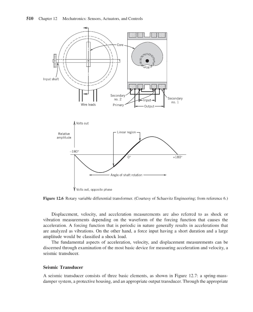
Figure 12.6 Rotary variable differential transformer. (Courtesy of Schaevitz Engineering; from reference 6.)
510 Chapter 12 Mechatronics: Sensors, Actuators, and Controls
13:54:9 Page 510
Displacement, velocity, and acceleration measurements are also referred to as shock or
vibration measurements depending on the waveform of the forcing function that causes the
acceleration. A forcing function that is periodic in nature generally results in accelerations that
are analyzed as vibrations. On the other hand, a force input having a short duration and a large
amplitude would be classified a shock load.
The fundamental aspects of acceleration, velocity, and displacement measurements can be
discerned through examination of the most basic device for measuring acceleration and velocity, a
seismic transducer.
Seismic Transducer
A seismic transducer consists of three basic elements, as shown in Figure 12.7: a spring-massdamper system, a protective housing, and an appropriate output transducer. Through the appropriate
–180°
0°
+180°
Volts out, opposite phase
Volts out
Relative
amplitude
Wire leads
Secondary
no. 2
Secondary
no. 1
Primary
Input shaft
Core
Output
Angle of shaft rotation
Input
Linear region
Figure 12.6 Rotary variable differential transformer. (Courtesy of Schaevitz Engineering; from reference 6.)
510 Chapter 12 Mechatronics: Sensors, Actuators, and Controls