

E1C10 09/14/2010
13:4:38 Page 436
KNOWN Fluid (of specific gravity S and specific weight g)
Manometer fluid (of specific gravity S m and specific weight g m )
ASSUMPTION Densities of the fluids remain constant.
FIND Q ¼ f ðHÞ
SOLUTION Equation 10.12 provides a relationship between flow rate and flow pressure drop.
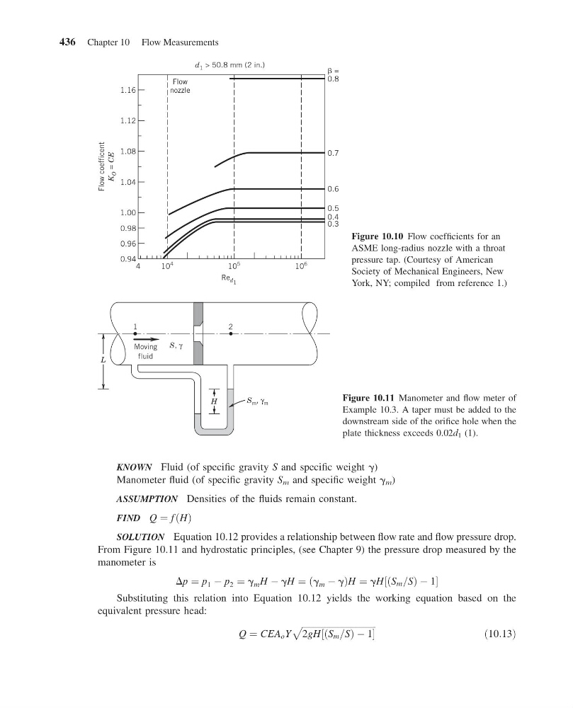
From Figure 10.11 and hydrostatic principles, (see Chapter 9) the pressure drop measured by the
manometer is
Dp ¼ p 1 À p 2 ¼ g m H À gH ¼ g m À g
ð
ÞH ¼ gH S m =S
ð
ÞÀ1
½
Substituting this relation into Equation 10.12 yields the working equation based on the
equivalent pressure head:
Q ¼ CEA o Y
ffiffiffiffiffiffiffiffiffiffiffiffiffiffiffiffiffiffiffiffiffiffiffiffiffiffiffiffiffiffiffiffiffi ffi
2gH S m =S
ð
ÞÀ1
½
p
ð10:13Þ
4
10
4
10
5
10
6
Re d 1
Flow coefficent
K
O =
CE
0.94
0.96
0.98
0.3
0.4
0.5
0.6
0.7
=
0.8
1.00
1.04
1.08
1.12
1.16
Flow
nozzle
d 1 > 50.8 mm (2 in.)
Figure 10.10 Flow coefficients for an
ASME long-radius nozzle with a throat
pressure tap. (Courtesy of American
Society of Mechanical Engineers, New
York, NY; compiled from reference 1.)
H
L
1
Moving
fluid
2
S m , γ m
S, γ
Figure 10.11 Manometer and flow meter of
Example 10.3. A taper must be added to the
downstream side of the orifice hole when the
plate thickness exceeds 0.02d 1 (1).
436 Chapter 10 Flow Measurements
13:4:38 Page 436
KNOWN Fluid (of specific gravity S and specific weight g)
Manometer fluid (of specific gravity S m and specific weight g m )
ASSUMPTION Densities of the fluids remain constant.
FIND Q ¼ f ðHÞ
SOLUTION Equation 10.12 provides a relationship between flow rate and flow pressure drop.
From Figure 10.11 and hydrostatic principles, (see Chapter 9) the pressure drop measured by the
manometer is
Dp ¼ p 1 À p 2 ¼ g m H À gH ¼ g m À g
ð
ÞH ¼ gH S m =S
ð
ÞÀ1
½
Substituting this relation into Equation 10.12 yields the working equation based on the
equivalent pressure head:
Q ¼ CEA o Y
ffiffiffiffiffiffiffiffiffiffiffiffiffiffiffiffiffiffiffiffiffiffiffiffiffiffiffiffiffiffiffiffiffi ffi
2gH S m =S
ð
ÞÀ1
½
p
ð10:13Þ
4
10
4
10
5
10
6
Re d 1
Flow coefficent
K
O =
CE
0.94
0.96
0.98
0.3
0.4
0.5
0.6
0.7
=
0.8
1.00
1.04
1.08
1.12
1.16
Flow
nozzle
d 1 > 50.8 mm (2 in.)
Figure 10.10 Flow coefficients for an
ASME long-radius nozzle with a throat
pressure tap. (Courtesy of American
Society of Mechanical Engineers, New
York, NY; compiled from reference 1.)
H
L
1
Moving
fluid
2
S m , γ m
S, γ
Figure 10.11 Manometer and flow meter of
Example 10.3. A taper must be added to the
downstream side of the orifice hole when the
plate thickness exceeds 0.02d 1 (1).
436 Chapter 10 Flow Measurements