

E1C10 09/14/2010
13:4:37 Page 429
where the subscript I emphasizes that Equation 10.7 gives an incompressible flow rate. Later we
drop the subscript.
When the flow area changes abruptly, the effective flow area immediately downstream of the
area reduction is not necessarily the same as the pipe flow area. This was originally investigated by
Jean Borda (1733–1799) and illustrated in Figure 10.3. When a fluid cannot exactly follow a sudden
area expansion due to its own inertia, a central core flow called the vena contracta forms that is
bounded by regions of slower moving recirculating eddies. The pressure sensed with pipe wall taps
corresponds to the higher moving velocity within the vena contracta with its unknown flow area, A 2 .
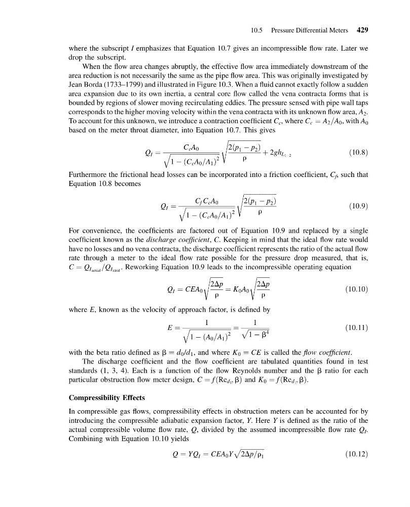
To account for this unknown, we introduce a contraction coefficient C c , where C c ¼ A 2 =A 0 , with A 0
based on the meter throat diameter, into Equation 10.7. This gives
Q I ¼
C c A 0
ffiffiffiffiffiffiffiffiffiffiffiffiffiffiffiffiffiffiffiffiffiffiffiffiffiffiffiffiffiffiffi ffi
1 À C c A 0 =A 1
ð
Þ
2
q
ffiffiffiffiffiffiffiffiffiffiffiffiffiffiffiffiffiffiffiffiffi
2 p 1 À p 2
ð
Þ
r
s
þ 2gh L 1À2
ð10:8Þ
Furthermore the frictional head losses can be incorporated into a friction coefficient, C f , such that
Equation 10.8 becomes
Q I ¼
C f C c A 0
ffiffiffiffiffiffiffiffiffiffiffiffiffiffiffiffiffiffiffiffiffiffiffiffiffiffiffiffiffiffiffi ffi
1 À C c A 0 =A 1
ð
Þ
2
q
ffiffiffiffiffiffiffiffiffiffiffiffiffiffiffiffiffiffiffiffiffi
2 p 1 À p 2
ð
Þ
r
s
ð10:9Þ
For convenience, the coefficients are factored out of Equation 10.9 and replaced by a single
coefficient known as the discharge coefficient, C. Keeping in mind that the ideal flow rate would
have no losses and no vena contracta, the discharge coefficient represents the ratio of the actual flow
rate through a meter to the ideal flow rate possible for the pressure drop measured, that is,
C ¼ Q I actual =Q I ideal . Reworking Equation 10.9 leads to the incompressible operating equation
Q I ¼ CEA 0
ffiffiffiffiffiffiffiffi ffi
2Dp
r
s
¼ K 0 A 0
ffiffiffiffiffiffiffiffi ffi
2Dp
r
s
ð10:10Þ
where E, known as the velocity of approach factor, is defined by
E ¼
1
ffiffiffiffiffiffiffiffiffiffiffiffiffiffiffiffiffiffiffiffiffiffiffiffiffiffi
1 À A 0 =A 1
ð
Þ
2
q
¼
1
ffiffiffiffiffiffiffiffiffiffiffiffiffi ffi
1 À b
4
p
ð10:11Þ
with the beta ratio defined as b ¼ d 0 /d 1 , and where K 0 ¼ CE is called the flow coefficient.
The discharge coefficient and the flow coefficient are tabulated quantities found in test
standards (1, 3, 4). Each is a function of the flow Reynolds number and the b ratio for each
particular obstruction flow meter design, C ¼ f Re d 1 ; b
ð
Þand K 0 ¼ f Re d 1 ; b
ð
Þ.
Compressibility Effects
In compressible gas flows, compressibility effects in obstruction meters can be accounted for by
introducing the compressible adiabatic expansion factor, Y. Here Y is defined as the ratio of the
actual compressible volume flow rate, Q, divided by the assumed incompressible flow rate Q I .
Combining with Equation 10.10 yields
Q ¼ YQ I ¼ CEA 0 Y
ffiffiffiffiffiffiffiffiffiffiffiffiffiffiffi
2Dp=r 1
p
ð10:12Þ
10.5 Pressure Differential Meters 429
13:4:37 Page 429
where the subscript I emphasizes that Equation 10.7 gives an incompressible flow rate. Later we
drop the subscript.
When the flow area changes abruptly, the effective flow area immediately downstream of the
area reduction is not necessarily the same as the pipe flow area. This was originally investigated by
Jean Borda (1733–1799) and illustrated in Figure 10.3. When a fluid cannot exactly follow a sudden
area expansion due to its own inertia, a central core flow called the vena contracta forms that is
bounded by regions of slower moving recirculating eddies. The pressure sensed with pipe wall taps
corresponds to the higher moving velocity within the vena contracta with its unknown flow area, A 2 .
To account for this unknown, we introduce a contraction coefficient C c , where C c ¼ A 2 =A 0 , with A 0
based on the meter throat diameter, into Equation 10.7. This gives
Q I ¼
C c A 0
ffiffiffiffiffiffiffiffiffiffiffiffiffiffiffiffiffiffiffiffiffiffiffiffiffiffiffiffiffiffiffi ffi
1 À C c A 0 =A 1
ð
Þ
2
q
ffiffiffiffiffiffiffiffiffiffiffiffiffiffiffiffiffiffiffiffiffi
2 p 1 À p 2
ð
Þ
r
s
þ 2gh L 1À2
ð10:8Þ
Furthermore the frictional head losses can be incorporated into a friction coefficient, C f , such that
Equation 10.8 becomes
Q I ¼
C f C c A 0
ffiffiffiffiffiffiffiffiffiffiffiffiffiffiffiffiffiffiffiffiffiffiffiffiffiffiffiffiffiffiffi ffi
1 À C c A 0 =A 1
ð
Þ
2
q
ffiffiffiffiffiffiffiffiffiffiffiffiffiffiffiffiffiffiffiffiffi
2 p 1 À p 2
ð
Þ
r
s
ð10:9Þ
For convenience, the coefficients are factored out of Equation 10.9 and replaced by a single
coefficient known as the discharge coefficient, C. Keeping in mind that the ideal flow rate would
have no losses and no vena contracta, the discharge coefficient represents the ratio of the actual flow
rate through a meter to the ideal flow rate possible for the pressure drop measured, that is,
C ¼ Q I actual =Q I ideal . Reworking Equation 10.9 leads to the incompressible operating equation
Q I ¼ CEA 0
ffiffiffiffiffiffiffiffi ffi
2Dp
r
s
¼ K 0 A 0
ffiffiffiffiffiffiffiffi ffi
2Dp
r
s
ð10:10Þ
where E, known as the velocity of approach factor, is defined by
E ¼
1
ffiffiffiffiffiffiffiffiffiffiffiffiffiffiffiffiffiffiffiffiffiffiffiffiffiffi
1 À A 0 =A 1
ð
Þ
2
q
¼
1
ffiffiffiffiffiffiffiffiffiffiffiffiffi ffi
1 À b
4
p
ð10:11Þ
with the beta ratio defined as b ¼ d 0 /d 1 , and where K 0 ¼ CE is called the flow coefficient.
The discharge coefficient and the flow coefficient are tabulated quantities found in test
standards (1, 3, 4). Each is a function of the flow Reynolds number and the b ratio for each
particular obstruction flow meter design, C ¼ f Re d 1 ; b
ð
Þand K 0 ¼ f Re d 1 ; b
ð
Þ.
Compressibility Effects
In compressible gas flows, compressibility effects in obstruction meters can be accounted for by
introducing the compressible adiabatic expansion factor, Y. Here Y is defined as the ratio of the
actual compressible volume flow rate, Q, divided by the assumed incompressible flow rate Q I .
Combining with Equation 10.10 yields
Q ¼ YQ I ¼ CEA 0 Y
ffiffiffiffiffiffiffiffiffiffiffiffiffiffiffi
2Dp=r 1
p
ð10:12Þ
10.5 Pressure Differential Meters 429