

E1C08 09/14/2010
14:54:4 Page 368
8.7 Research and describe current state-of-the-art electronic modules to measure temperature using an
RTD sensor. List typical specifications that could be used in a design stage uncertainty analysis.
8.8 Estimate the required level of uncertainty in the measurement of resistance for a platinum RTD if
it is to serve as a local standard for the calibration of a temperature measurement system for an
uncertainty of Æ0.005
C. Assume R(0
C) ¼ 100 V.
8.9 A thermistor is placed in a 100
C environment, and its resistance measured as 20,000 V. The
material constant, b, for this thermistor is 3650
C. If the thermistor is then used to measure a
particular temperature, and its resistance is measured as 500 V, determine the thermistor
temperature.
8.10 Using a spreadsheet or similar software, reproduce Figure 8.11.
8.11 Define and discuss the following terms related to thermocouple circuits:
a. thermocouple junction
b. thermocouple laws
c. reference junction
d. Peltier effect
e. Seebeck coefficient
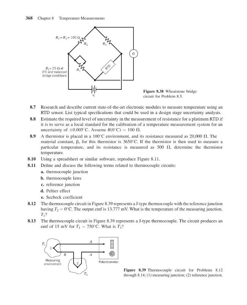
8.12 The thermocouple circuit in Figure 8.39 represents a J-type thermocouple with the reference junction
having T 2 ¼ 0
C. The output emf is 13.777 mV. What is the temperature of the measuring junction,
T 1 ?
8.13 The thermocouple circuit in Figure 8.39 represents a J-type thermocouple. The circuit produces an
emf of 15 mV for T 1 ¼ 750
C. What is T 2 ?
R 1
R 1 = 25 Ω at
0 C and balanced
bridge conditions
R 3
R 2
e i
G
R T D
R 2 = R 3 = 100 Ω
Figure 8.38 Wheatstone bridge
circuit for Problem 8.5.
A
A
B
T 1
T 2
2
Measuring
environment
1
Potentiometer
Figure 8.39 Thermocouple circuit for Problems 8.12
through 8.14; (1) measuring junction; (2) reference junction.
368 Chapter 8 Temperature Measurements
14:54:4 Page 368
8.7 Research and describe current state-of-the-art electronic modules to measure temperature using an
RTD sensor. List typical specifications that could be used in a design stage uncertainty analysis.
8.8 Estimate the required level of uncertainty in the measurement of resistance for a platinum RTD if
it is to serve as a local standard for the calibration of a temperature measurement system for an
uncertainty of Æ0.005
C. Assume R(0
C) ¼ 100 V.
8.9 A thermistor is placed in a 100
C environment, and its resistance measured as 20,000 V. The
material constant, b, for this thermistor is 3650
C. If the thermistor is then used to measure a
particular temperature, and its resistance is measured as 500 V, determine the thermistor
temperature.
8.10 Using a spreadsheet or similar software, reproduce Figure 8.11.
8.11 Define and discuss the following terms related to thermocouple circuits:
a. thermocouple junction
b. thermocouple laws
c. reference junction
d. Peltier effect
e. Seebeck coefficient
8.12 The thermocouple circuit in Figure 8.39 represents a J-type thermocouple with the reference junction
having T 2 ¼ 0
C. The output emf is 13.777 mV. What is the temperature of the measuring junction,
T 1 ?
8.13 The thermocouple circuit in Figure 8.39 represents a J-type thermocouple. The circuit produces an
emf of 15 mV for T 1 ¼ 750
C. What is T 2 ?
R 1
R 1 = 25 Ω at
0 C and balanced
bridge conditions
R 3
R 2
e i
G
R T D
R 2 = R 3 = 100 Ω
Figure 8.38 Wheatstone bridge
circuit for Problem 8.5.
A
A
B
T 1
T 2
2
Measuring
environment
1
Potentiometer
Figure 8.39 Thermocouple circuit for Problems 8.12
through 8.14; (1) measuring junction; (2) reference junction.
368 Chapter 8 Temperature Measurements