

E1C08 09/14/2010
14:53:57 Page 324
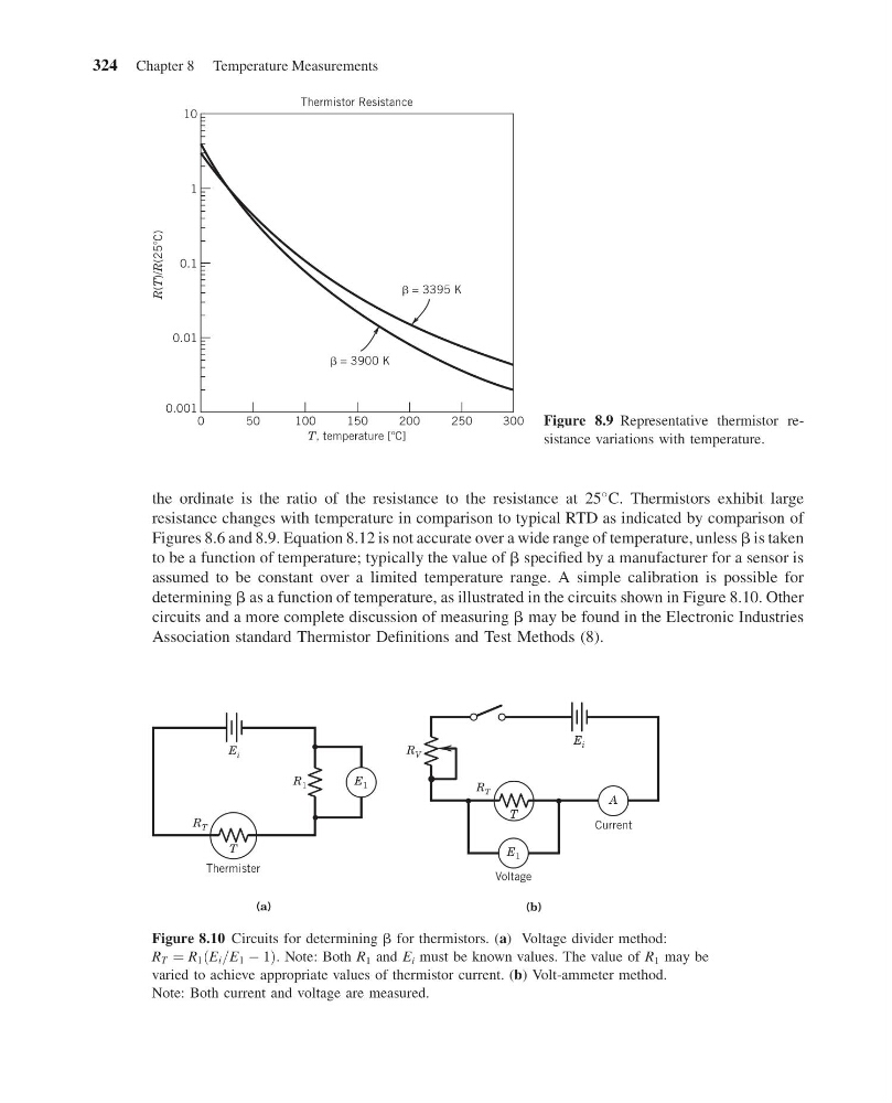
the ordinate is the ratio of the resistance to the resistance at 25
C. Thermistors exhibit large
resistance changes with temperature in comparison to typical RTD as indicated by comparison of
Figures 8.6 and 8.9. Equation 8.12 is not accurate over a wide range of temperature, unless b is taken
to be a function of temperature; typically the value of b specified by a manufacturer for a sensor is
assumed to be constant over a limited temperature range. A simple calibration is possible for
determining b as a function of temperature, as illustrated in the circuits shown in Figure 8.10. Other
circuits and a more complete discussion of measuring b may be found in the Electronic Industries
Association standard Thermistor Definitions and Test Methods (8).
0
50
100
150
200
250
300
T, temperature [ C]
Thermistor Resistance
R(T)/R(25 C)
0.001
0.01
0.1
1
10
= 3395 K
= 3900 K
Figure 8.9 Representative thermistor resistance variations with temperature.
R 1
Thermister
Voltage
Current
(a)
T
(b)
E 1
E 1
E i
E i
R T
R T
A
R V
T
Figure 8.10 Circuits for determining b for thermistors. (a) Voltage divider method:
R T ¼ R 1 E i =E 1 À 1
ð
Þ . Note: Both R 1 and E i must be known values. The value of R 1 may be
varied to achieve appropriate values of thermistor current. (b) Volt-ammeter method.
Note: Both current and voltage are measured.
324 Chapter 8 Temperature Measurements
14:53:57 Page 324
the ordinate is the ratio of the resistance to the resistance at 25
C. Thermistors exhibit large
resistance changes with temperature in comparison to typical RTD as indicated by comparison of
Figures 8.6 and 8.9. Equation 8.12 is not accurate over a wide range of temperature, unless b is taken
to be a function of temperature; typically the value of b specified by a manufacturer for a sensor is
assumed to be constant over a limited temperature range. A simple calibration is possible for
determining b as a function of temperature, as illustrated in the circuits shown in Figure 8.10. Other
circuits and a more complete discussion of measuring b may be found in the Electronic Industries
Association standard Thermistor Definitions and Test Methods (8).
0
50
100
150
200
250
300
T, temperature [ C]
Thermistor Resistance
R(T)/R(25 C)
0.001
0.01
0.1
1
10
= 3395 K
= 3900 K
Figure 8.9 Representative thermistor resistance variations with temperature.
R 1
Thermister
Voltage
Current
(a)
T
(b)
E 1
E 1
E i
E i
R T
R T
A
R V
T
Figure 8.10 Circuits for determining b for thermistors. (a) Voltage divider method:
R T ¼ R 1 E i =E 1 À 1
ð
Þ . Note: Both R 1 and E i must be known values. The value of R 1 may be
varied to achieve appropriate values of thermistor current. (b) Volt-ammeter method.
Note: Both current and voltage are measured.
324 Chapter 8 Temperature Measurements