

E1C06 09/14/2010
11:55:7 Page 251
equipment or building wiring on their return path to earth. Thus, if a signal is grounded at two points,
say at a power source ground and then at an earth ground, the two grounds could be at different
voltage levels. The difference between the two ground point voltages is called the common-mode
voltage (cmv). This can lead to problems, as discussed next.
Ground loops are caused by connecting a signal circuit to two or more grounds that are at
different potentials. A ground wire of finite resistance usually carries some current, and so it
develops a potential. Thus two separate and different grounds, even two in close proximity, can be
at different potential levels. So when these ground points are connected into a circuit the potential
difference itself drives a small unwanted current. The result is a ground loop—an electrical
interference superimposed onto the signal. A ground loop can manifest itself in various forms, such
as a sinusoidal signal or simply a voltage offset.
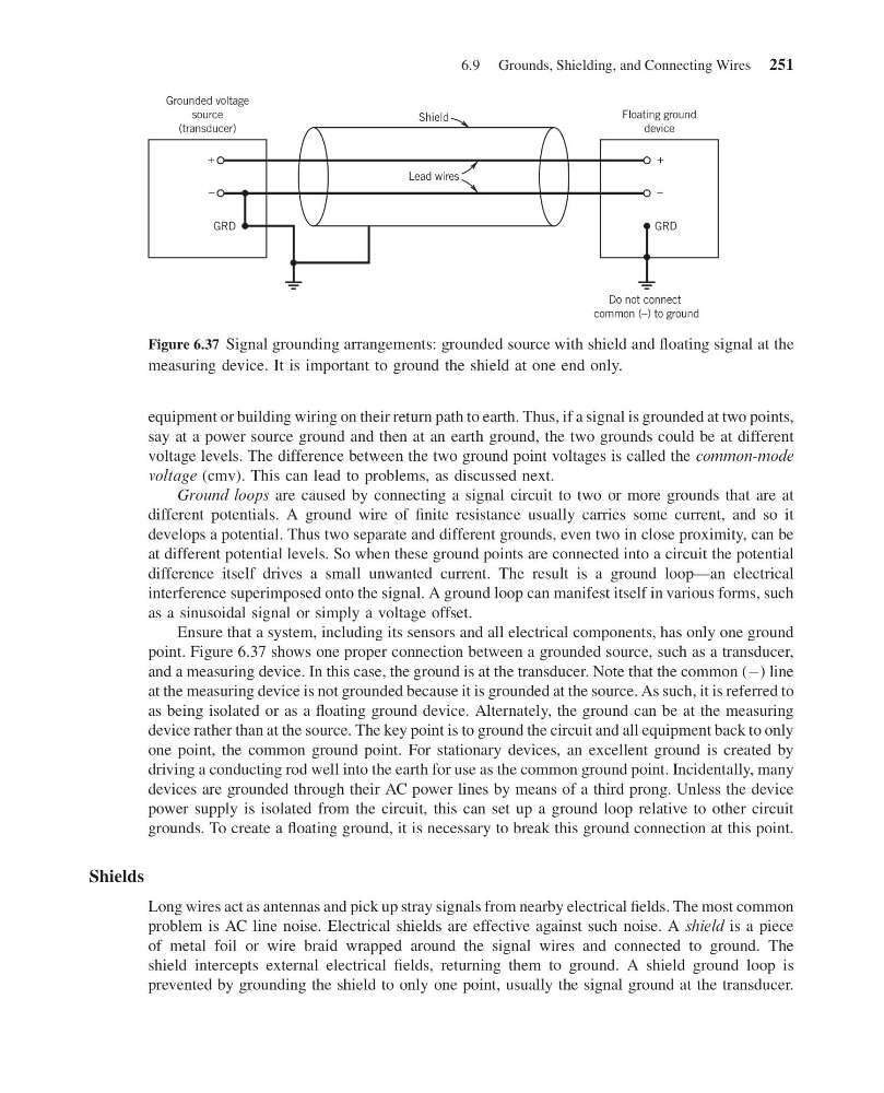
Ensure that a system, including its sensors and all electrical components, has only one ground
point. Figure 6.37 shows one proper connection between a grounded source, such as a transducer,
and a measuring device. In this case, the ground is at the transducer. Note that the common (À) line
at the measuring device is not grounded because it is grounded at the source. As such, it is referred to
as being isolated or as a floating ground device. Alternately, the ground can be at the measuring
device rather than at the source. The key point is to ground the circuit and all equipment back to only
one point, the common ground point. For stationary devices, an excellent ground is created by
driving a conducting rod well into the earth for use as the common ground point. Incidentally, many
devices are grounded through their AC power lines by means of a third prong. Unless the device
power supply is isolated from the circuit, this can set up a ground loop relative to other circuit
grounds. To create a floating ground, it is necessary to break this ground connection at this point.
Shields
Long wires act as antennas and pick up stray signals from nearby electrical fields. The most common
problem is AC line noise. Electrical shields are effective against such noise. A shield is a piece
of metal foil or wire braid wrapped around the signal wires and connected to ground. The
shield intercepts external electrical fields, returning them to ground. A shield ground loop is
prevented by grounding the shield to only one point, usually the signal ground at the transducer.
GRD
GRD
+
Lead wires
Shield
–
+
–
Grounded voltage
source
(transducer)
Floating ground
device
Do not connect
common (–) to ground
Figure 6.37 Signal grounding arrangements: grounded source with shield and floating signal at the
measuring device. It is important to ground the shield at one end only.
6.9 Grounds, Shielding, and Connecting Wires 251
11:55:7 Page 251
equipment or building wiring on their return path to earth. Thus, if a signal is grounded at two points,
say at a power source ground and then at an earth ground, the two grounds could be at different
voltage levels. The difference between the two ground point voltages is called the common-mode
voltage (cmv). This can lead to problems, as discussed next.
Ground loops are caused by connecting a signal circuit to two or more grounds that are at
different potentials. A ground wire of finite resistance usually carries some current, and so it
develops a potential. Thus two separate and different grounds, even two in close proximity, can be
at different potential levels. So when these ground points are connected into a circuit the potential
difference itself drives a small unwanted current. The result is a ground loop—an electrical
interference superimposed onto the signal. A ground loop can manifest itself in various forms, such
as a sinusoidal signal or simply a voltage offset.
Ensure that a system, including its sensors and all electrical components, has only one ground
point. Figure 6.37 shows one proper connection between a grounded source, such as a transducer,
and a measuring device. In this case, the ground is at the transducer. Note that the common (À) line
at the measuring device is not grounded because it is grounded at the source. As such, it is referred to
as being isolated or as a floating ground device. Alternately, the ground can be at the measuring
device rather than at the source. The key point is to ground the circuit and all equipment back to only
one point, the common ground point. For stationary devices, an excellent ground is created by
driving a conducting rod well into the earth for use as the common ground point. Incidentally, many
devices are grounded through their AC power lines by means of a third prong. Unless the device
power supply is isolated from the circuit, this can set up a ground loop relative to other circuit
grounds. To create a floating ground, it is necessary to break this ground connection at this point.
Shields
Long wires act as antennas and pick up stray signals from nearby electrical fields. The most common
problem is AC line noise. Electrical shields are effective against such noise. A shield is a piece
of metal foil or wire braid wrapped around the signal wires and connected to ground. The
shield intercepts external electrical fields, returning them to ground. A shield ground loop is
prevented by grounding the shield to only one point, usually the signal ground at the transducer.
GRD
GRD
+
Lead wires
Shield
–
+
–
Grounded voltage
source
(transducer)
Floating ground
device
Do not connect
common (–) to ground
Figure 6.37 Signal grounding arrangements: grounded source with shield and floating signal at the
measuring device. It is important to ground the shield at one end only.
6.9 Grounds, Shielding, and Connecting Wires 251