

E1C06 09/14/2010
11:55:7 Page 249
with static sensitivity (or gain) of K ¼ R 2 /R 1 . The magnitude ratio is given by
M f
ð Þ ¼
1
1 þ f c =f
ð
Þ
2
h
i 1=2
ð6:68Þ
An active inverting bandpass filter can be formed by combining the high- and low-pass filters
above and is shown in Figure 6.35c. The low cutoff frequency f c 1 is given by Equation 6.66 and the
high cutoff frequency f c 2 by Equation 6.67. This simple circuit is limited in the width of its bandpass.
A narrow bandpass requires a higher order filter than the one shown. The design of active filters can
be studied with the accompanying LabView program Lowpass Butterworth Active Filter.
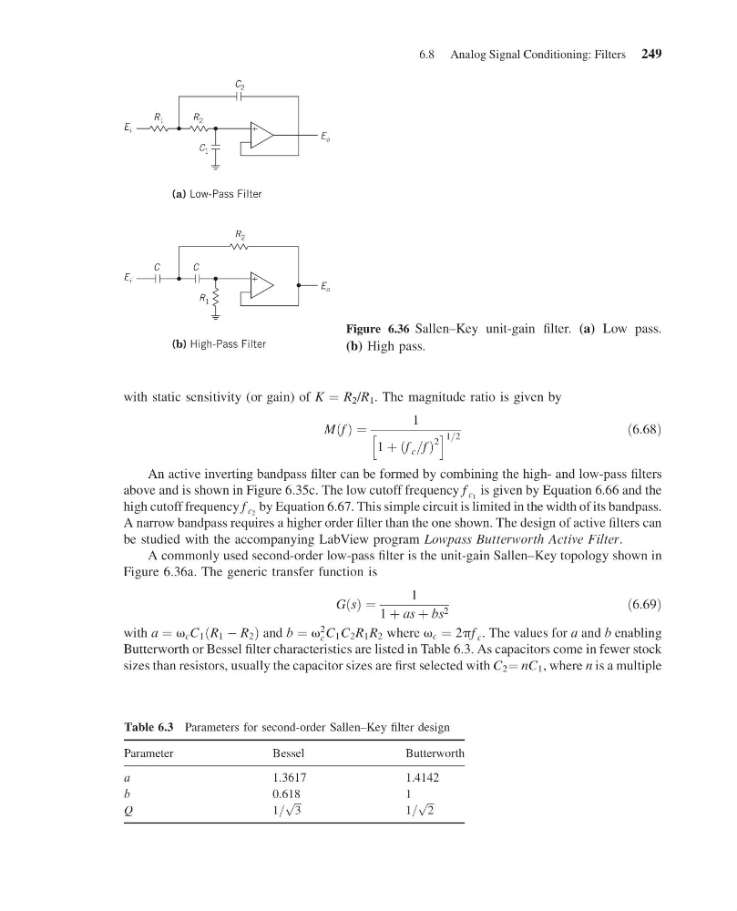
A commonly used second-order low-pass filter is the unit-gain Sallen–Key topology shown in
Figure 6.36a. The generic transfer function is
GðsÞ ¼
1
1 þ as þ bs 2
ð6:69Þ
with a ¼ v c C 1 ðR 1 À R 2 Þ and b ¼ v
2
c C 1 C 2 R 1 R 2 where v c ¼ 2pf c . The values for a and b enabling
Butterworth or Bessel filter characteristics are listed in Table 6.3. As capacitors come in fewer stock
sizes than resistors, usually the capacitor sizes are first selected with C 2 ¼ nC 1 , where n is a multiple
E i
E o
R 1
R 2
C 2
+
C 1
(a) Low-Pass Filter
E i
E o
C
C
R 2
+
R 1
(b) High-Pass Filter
Figure 6.36 Sallen–Key unit-gain filter. (a) Low pass.
(b) High pass.
Table 6.3 Parameters for second-order Sallen–Key filter design
Parameter
Bessel
Butterworth
a
1.3617
1.4142
b
0.618
1
Q
1=
ffiffi ffi
3
p
1=
ffiffi ffi
2
p
6.8 Analog Signal Conditioning: Filters 249
11:55:7 Page 249
with static sensitivity (or gain) of K ¼ R 2 /R 1 . The magnitude ratio is given by
M f
ð Þ ¼
1
1 þ f c =f
ð
Þ
2
h
i 1=2
ð6:68Þ
An active inverting bandpass filter can be formed by combining the high- and low-pass filters
above and is shown in Figure 6.35c. The low cutoff frequency f c 1 is given by Equation 6.66 and the
high cutoff frequency f c 2 by Equation 6.67. This simple circuit is limited in the width of its bandpass.
A narrow bandpass requires a higher order filter than the one shown. The design of active filters can
be studied with the accompanying LabView program Lowpass Butterworth Active Filter.
A commonly used second-order low-pass filter is the unit-gain Sallen–Key topology shown in
Figure 6.36a. The generic transfer function is
GðsÞ ¼
1
1 þ as þ bs 2
ð6:69Þ
with a ¼ v c C 1 ðR 1 À R 2 Þ and b ¼ v
2
c C 1 C 2 R 1 R 2 where v c ¼ 2pf c . The values for a and b enabling
Butterworth or Bessel filter characteristics are listed in Table 6.3. As capacitors come in fewer stock
sizes than resistors, usually the capacitor sizes are first selected with C 2 ¼ nC 1 , where n is a multiple
E i
E o
R 1
R 2
C 2
+
C 1
(a) Low-Pass Filter
E i
E o
C
C
R 2
+
R 1
(b) High-Pass Filter
Figure 6.36 Sallen–Key unit-gain filter. (a) Low pass.
(b) High pass.
Table 6.3 Parameters for second-order Sallen–Key filter design
Parameter
Bessel
Butterworth
a
1.3617
1.4142
b
0.618
1
Q
1=
ffiffi ffi
3
p
1=
ffiffi ffi
2
p
6.8 Analog Signal Conditioning: Filters 249