

E1C06 09/14/2010
11:55:2 Page 210
6.2 ANALOG DEVICES: CURRENT MEASUREMENTS
Direct Current
One way to measure a DC electrical current is to use an analog device that responds to the force
exerted on a current-carrying conductor in a magnetic field. Because an electric current is a series of
moving charges, a magnetic field exerts a force on a current-carrying conductor. This force can be
used as a measure of the flow of current in a conductor by moving a pointer on a display.
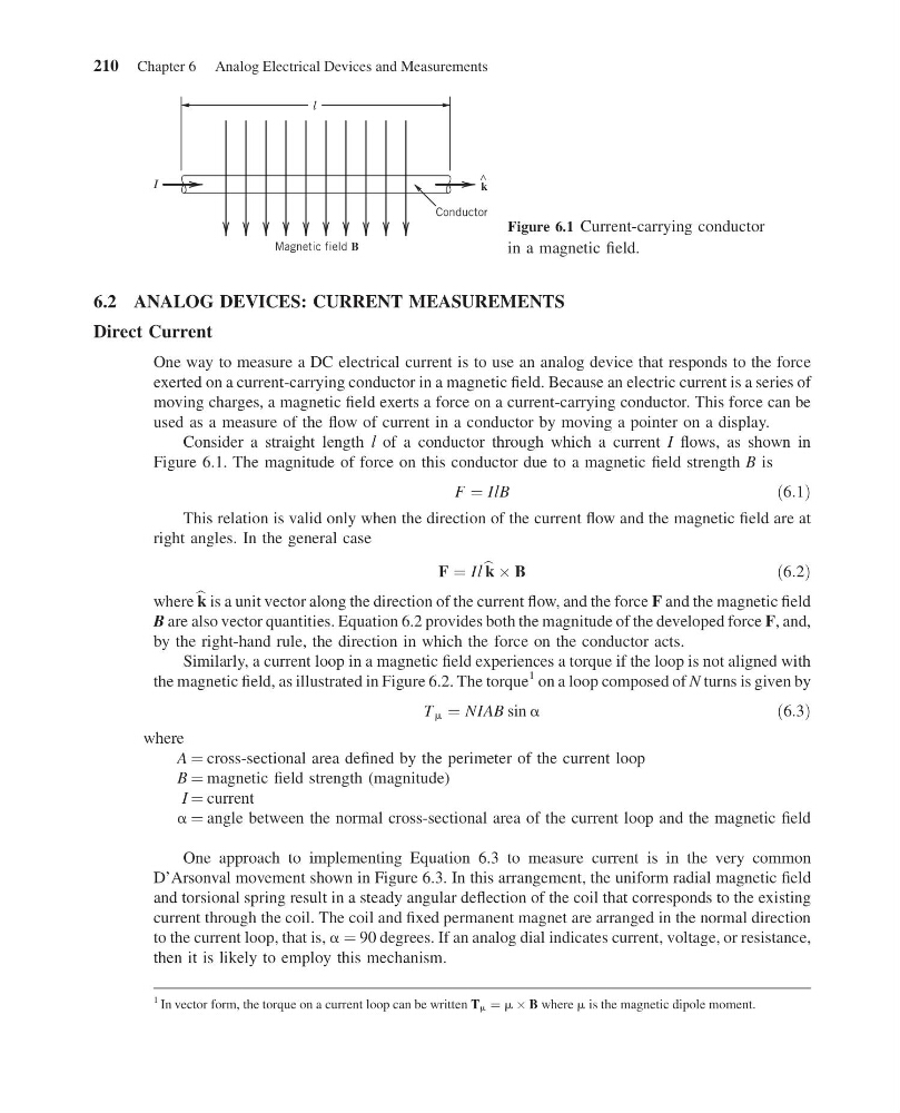
Consider a straight length l of a conductor through which a current I flows, as shown in
Figure 6.1. The magnitude of force on this conductor due to a magnetic field strength B is
F ¼ IlB
ð6:1Þ
This relation is valid only when the direction of the current flow and the magnetic field are at
right angles. In the general case
F ¼ Il b k  B
ð6:2Þ
where b k is a unit vector along the direction of the current flow, and the force F and the magnetic field
B are also vector quantities. Equation 6.2 provides both the magnitude of the developed force F, and,
by the right-hand rule, the direction in which the force on the conductor acts.
Similarly, a current loop in a magnetic field experiences a torque if the loop is not aligned with
the magnetic field, as illustrated in Figure 6.2. The torque
1 on a loop composed of N turns is given by
T m ¼ NIAB sin a
ð6:3Þ
where
A ¼ cross-sectional area defined by the perimeter of the current loop
B ¼ magnetic field strength (magnitude)
I ¼ current
a ¼ angle between the normal cross-sectional area of the current loop and the magnetic field
One approach to implementing Equation 6.3 to measure current is in the very common
D’Arsonval movement shown in Figure 6.3. In this arrangement, the uniform radial magnetic field
and torsional spring result in a steady angular deflection of the coil that corresponds to the existing
current through the coil. The coil and fixed permanent magnet are arranged in the normal direction
to the current loop, that is, a ¼ 90 degrees. If an analog dial indicates current, voltage, or resistance,
then it is likely to employ this mechanism.
Magnetic field B
Conductor
^
l
I
k
Figure 6.1 Current-carrying conductor
in a magnetic field.
1 In vector form, the torque on a current loop can be written T m ¼ m  B where m is the magnetic dipole moment.
210 Chapter 6 Analog Electrical Devices and Measurements
11:55:2 Page 210
6.2 ANALOG DEVICES: CURRENT MEASUREMENTS
Direct Current
One way to measure a DC electrical current is to use an analog device that responds to the force
exerted on a current-carrying conductor in a magnetic field. Because an electric current is a series of
moving charges, a magnetic field exerts a force on a current-carrying conductor. This force can be
used as a measure of the flow of current in a conductor by moving a pointer on a display.
Consider a straight length l of a conductor through which a current I flows, as shown in
Figure 6.1. The magnitude of force on this conductor due to a magnetic field strength B is
F ¼ IlB
ð6:1Þ
This relation is valid only when the direction of the current flow and the magnetic field are at
right angles. In the general case
F ¼ Il b k  B
ð6:2Þ
where b k is a unit vector along the direction of the current flow, and the force F and the magnetic field
B are also vector quantities. Equation 6.2 provides both the magnitude of the developed force F, and,
by the right-hand rule, the direction in which the force on the conductor acts.
Similarly, a current loop in a magnetic field experiences a torque if the loop is not aligned with
the magnetic field, as illustrated in Figure 6.2. The torque
1 on a loop composed of N turns is given by
T m ¼ NIAB sin a
ð6:3Þ
where
A ¼ cross-sectional area defined by the perimeter of the current loop
B ¼ magnetic field strength (magnitude)
I ¼ current
a ¼ angle between the normal cross-sectional area of the current loop and the magnetic field
One approach to implementing Equation 6.3 to measure current is in the very common
D’Arsonval movement shown in Figure 6.3. In this arrangement, the uniform radial magnetic field
and torsional spring result in a steady angular deflection of the coil that corresponds to the existing
current through the coil. The coil and fixed permanent magnet are arranged in the normal direction
to the current loop, that is, a ¼ 90 degrees. If an analog dial indicates current, voltage, or resistance,
then it is likely to employ this mechanism.
Magnetic field B
Conductor
^
l
I
k
Figure 6.1 Current-carrying conductor
in a magnetic field.
1 In vector form, the torque on a current loop can be written T m ¼ m  B where m is the magnetic dipole moment.
210 Chapter 6 Analog Electrical Devices and Measurements