

2.5 Thermodynamic Engines
79
ln V
ln P
1
2
3
4
(a) CCW cycle 1
T max
T high
T low
T min
ln V
ln P
1
2
3
4
(b) CCW cycle 2
T max
T high
T low
T min
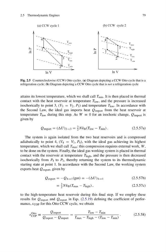
Fig. 2.5 Counterclockwise (CCW) Otto cycles. (a) Diagram depicting a CCW Otto cycle that is a
refrigeration cycle; (b) Diagram depicting a CCW Otto cycle that is not a refrigeration cycle
attains its lowest temperature, which we shall call T min . It is then placed in thermal
contact with the heat reservoir at temperature T low , and the pressure is increased
isochorically to point 3, (V 3 = V 2 , P 3 ) and temperature T low . In accordance with
the Second Law, the ideal gas imports heat Q import from the heat reservoir at
temperature T low during this step. As W ≡ 0 for an isochoric change, Q import is
given by
Q import = ((U ) 2→3 =
3
2 Nk B (T low − T min ) .
(2.5.57a)
The system is again isolated from the two heat reservoirs and is compressed
adiabatically to point 4, (V 4 = V 1 , P 4 ), with the ideal gas achieving its highest
temperature, which we shall call T max : this compression requires external work, W ,
to be done on the system. Finally, the ideal gas working system is placed in thermal
contact with the reservoir at temperature T high , and the pressure is then decreased
isochorically from P 4 to P 1 , thereby returning the system to its thermodynamic
starting state at point 1. In accordance with the Second Law, the working system
exports heat Q export , given by
Q export = −Q 4→1 (gas) ≡ −((U ) 4→1
(2.5.57b)
=
3
2 Nk B (T max − T high ) ,
(2.5.57c)
to the high-temperature heat reservoir during this final step. If we employ these
results for Q import and Q export in Eqs. (2.5.19) defining the coefficient of performance, ε COP for this Otto CCW cycle, we obtain
ε
Otto
COP ≡
Q import
Q export − Q import
=
T low − T min
T max − T high − (T low − T min )
.
(2.5.58)
79
ln V
ln P
1
2
3
4
(a) CCW cycle 1
T max
T high
T low
T min
ln V
ln P
1
2
3
4
(b) CCW cycle 2
T max
T high
T low
T min
Fig. 2.5 Counterclockwise (CCW) Otto cycles. (a) Diagram depicting a CCW Otto cycle that is a
refrigeration cycle; (b) Diagram depicting a CCW Otto cycle that is not a refrigeration cycle
attains its lowest temperature, which we shall call T min . It is then placed in thermal
contact with the heat reservoir at temperature T low , and the pressure is increased
isochorically to point 3, (V 3 = V 2 , P 3 ) and temperature T low . In accordance with
the Second Law, the ideal gas imports heat Q import from the heat reservoir at
temperature T low during this step. As W ≡ 0 for an isochoric change, Q import is
given by
Q import = ((U ) 2→3 =
3
2 Nk B (T low − T min ) .
(2.5.57a)
The system is again isolated from the two heat reservoirs and is compressed
adiabatically to point 4, (V 4 = V 1 , P 4 ), with the ideal gas achieving its highest
temperature, which we shall call T max : this compression requires external work, W ,
to be done on the system. Finally, the ideal gas working system is placed in thermal
contact with the reservoir at temperature T high , and the pressure is then decreased
isochorically from P 4 to P 1 , thereby returning the system to its thermodynamic
starting state at point 1. In accordance with the Second Law, the working system
exports heat Q export , given by
Q export = −Q 4→1 (gas) ≡ −((U ) 4→1
(2.5.57b)
=
3
2 Nk B (T max − T high ) ,
(2.5.57c)
to the high-temperature heat reservoir during this final step. If we employ these
results for Q import and Q export in Eqs. (2.5.19) defining the coefficient of performance, ε COP for this Otto CCW cycle, we obtain
ε
Otto
COP ≡
Q import
Q export − Q import
=
T low − T min
T max − T high − (T low − T min )
.
(2.5.58)