

64
2 Basic Elements of Spintronics
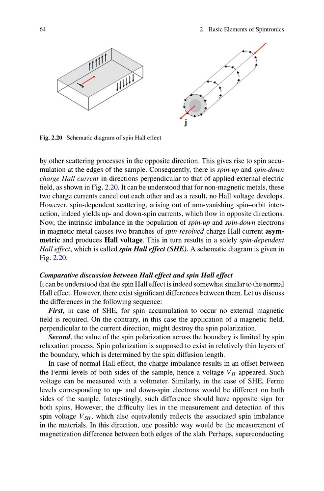
Fig. 2.20 Schematic diagram of spin Hall effect
by other scattering processes in the opposite direction. This gives rise to spin accumulation at the edges of the sample. Consequently, there is spin-up and spin-down
charge Hall current in directions perpendicular to that of applied external electric
field, as shown in Fig. 2.20. It can be understood that for non-magnetic metals, these
two charge currents cancel out each other and as a result, no Hall voltage develops.
However, spin-dependent scattering, arising out of non-vanishing spin–orbit interaction, indeed yields up- and down-spin currents, which flow in opposite directions.
Now, the intrinsic imbalance in the population of spin-up and spin-down electrons
in magnetic metal causes two branches of spin-resolved charge Hall current asymmetric and produces Hall voltage. This in turn results in a solely spin-dependent
Hall effect, which is called spin Hall effect (SHE). A schematic diagram is given in
Fig. 2.20.
Comparative discussion between Hall effect and spin Hall effect
It can be understood that the spin Hall effect is indeed somewhat similar to the normal
Hall effect. However, there exist significant differences between them. Let us discuss
the differences in the following sequence:
First, in case of SHE, for spin accumulation to occur no external magnetic
field is required. On the contrary, in this case the application of a magnetic field,
perpendicular to the current direction, might destroy the spin polarization.
Second, the value of the spin polarization across the boundary is limited by spin
relaxation process. Spin polarization is supposed to exist in relatively thin layers of
the boundary, which is determined by the spin diffusion length.
In case of normal Hall effect, the charge imbalance results in an offset between
the Fermi levels of both sides of the sample, hence a voltage V H appeared. Such
voltage can be measured with a voltmeter. Similarly, in the case of SHE, Fermi
levels corresponding to up- and down-spin electrons would be different on both
sides of the sample. Interestingly, such difference should have opposite sign for
both spins. However, the difficulty lies in the measurement and detection of this
spin voltage V SH , which also equivalently reflects the associated spin imbalance
in the materials. In this direction, one possible way would be the measurement of
magnetization difference between both edges of the slab. Perhaps, superconducting
2 Basic Elements of Spintronics
Fig. 2.20 Schematic diagram of spin Hall effect
by other scattering processes in the opposite direction. This gives rise to spin accumulation at the edges of the sample. Consequently, there is spin-up and spin-down
charge Hall current in directions perpendicular to that of applied external electric
field, as shown in Fig. 2.20. It can be understood that for non-magnetic metals, these
two charge currents cancel out each other and as a result, no Hall voltage develops.
However, spin-dependent scattering, arising out of non-vanishing spin–orbit interaction, indeed yields up- and down-spin currents, which flow in opposite directions.
Now, the intrinsic imbalance in the population of spin-up and spin-down electrons
in magnetic metal causes two branches of spin-resolved charge Hall current asymmetric and produces Hall voltage. This in turn results in a solely spin-dependent
Hall effect, which is called spin Hall effect (SHE). A schematic diagram is given in
Fig. 2.20.
Comparative discussion between Hall effect and spin Hall effect
It can be understood that the spin Hall effect is indeed somewhat similar to the normal
Hall effect. However, there exist significant differences between them. Let us discuss
the differences in the following sequence:
First, in case of SHE, for spin accumulation to occur no external magnetic
field is required. On the contrary, in this case the application of a magnetic field,
perpendicular to the current direction, might destroy the spin polarization.
Second, the value of the spin polarization across the boundary is limited by spin
relaxation process. Spin polarization is supposed to exist in relatively thin layers of
the boundary, which is determined by the spin diffusion length.
In case of normal Hall effect, the charge imbalance results in an offset between
the Fermi levels of both sides of the sample, hence a voltage V H appeared. Such
voltage can be measured with a voltmeter. Similarly, in the case of SHE, Fermi
levels corresponding to up- and down-spin electrons would be different on both
sides of the sample. Interestingly, such difference should have opposite sign for
both spins. However, the difficulty lies in the measurement and detection of this
spin voltage V SH , which also equivalently reflects the associated spin imbalance
in the materials. In this direction, one possible way would be the measurement of
magnetization difference between both edges of the slab. Perhaps, superconducting