

254
10 Spintronics Applications
and the spread of spin precession angles. Supriyo Datta said that they were inspired
by optical phenomena to put forward the concept of spin transistor. Electronic device
was proposed similar to optical devices by exploiting the similarities between the
spin of an electron and the polarization of a photon.
10.7.1 Working of Spin FET
The basic idea of the spin FET, as proposed by Datta and Das, is to control the
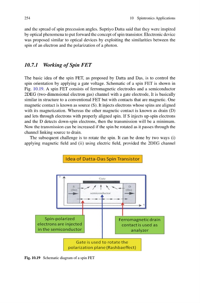
spin orientation by applying a gate voltage. Schematic of a spin FET is shown in
Fig. 10.19. A spin FET consists of ferromagnetic electrodes and a semiconductor
2DEG (two-dimensional electron gas) channel with a gate electrode, It is basically
similar in structure to a conventional FET but with contacts that are magnetic. One
magnetic contact is known as source (S). It injects electrons whose spins are aligned
with its magnetization. Whereas the other magnetic contact is known as drain (D)
and lets through electrons with properly aligned spin. If S injects up-spin electrons
and the D detects down-spin electrons, then the transmission will be a minimum.
Now the transmission can be increased if the spin be rotated as it passes through the
channel linking source to drain.
The subsequent challenge is to rotate the spin. It can be done by two ways (i)
applying magnetic field and (ii) using electric field, provided the 2DEG channel
Fig. 10.19 Schematic diagram of a spin FET
10 Spintronics Applications
and the spread of spin precession angles. Supriyo Datta said that they were inspired
by optical phenomena to put forward the concept of spin transistor. Electronic device
was proposed similar to optical devices by exploiting the similarities between the
spin of an electron and the polarization of a photon.
10.7.1 Working of Spin FET
The basic idea of the spin FET, as proposed by Datta and Das, is to control the
spin orientation by applying a gate voltage. Schematic of a spin FET is shown in
Fig. 10.19. A spin FET consists of ferromagnetic electrodes and a semiconductor
2DEG (two-dimensional electron gas) channel with a gate electrode, It is basically
similar in structure to a conventional FET but with contacts that are magnetic. One
magnetic contact is known as source (S). It injects electrons whose spins are aligned
with its magnetization. Whereas the other magnetic contact is known as drain (D)
and lets through electrons with properly aligned spin. If S injects up-spin electrons
and the D detects down-spin electrons, then the transmission will be a minimum.
Now the transmission can be increased if the spin be rotated as it passes through the
channel linking source to drain.
The subsequent challenge is to rotate the spin. It can be done by two ways (i)
applying magnetic field and (ii) using electric field, provided the 2DEG channel
Fig. 10.19 Schematic diagram of a spin FET