

6.4 Domain Wall Motion Velocity Measurements
155
et al. 2001; Parkin 2004; Numata et al. 2007; Levy and Zhang 1997; Lepadatu and
Xu 2004; Versluijs et al. 2001; García et al. 1999; Lepadatu et al. 2005; Himeno
et al. 2004; Atkinson et al. 2003). In order to determine domain wall velocity in
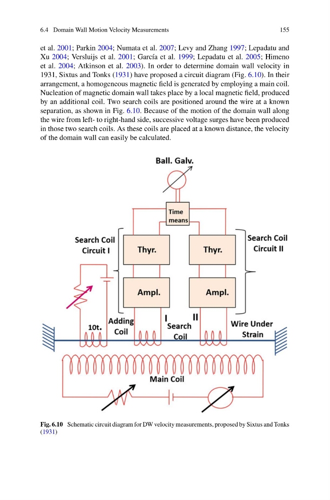
1931, Sixtus and Tonks (1931) have proposed a circuit diagram (Fig. 6.10). In their
arrangement, a homogeneous magnetic field is generated by employing a main coil.
Nucleation of magnetic domain wall takes place by a local magnetic field, produced
by an additional coil. Two search coils are positioned around the wire at a known
separation, as shown in Fig. 6.10. Because of the motion of the domain wall along
the wire from left- to right-hand side, successive voltage surges have been produced
in those two search coils. As these coils are placed at a known distance, the velocity
of the domain wall can easily be calculated.
Fig. 6.10 Schematic circuit diagram for DW velocity measurements, proposed by Sixtus and Tonks
(1931)
155
et al. 2001; Parkin 2004; Numata et al. 2007; Levy and Zhang 1997; Lepadatu and
Xu 2004; Versluijs et al. 2001; García et al. 1999; Lepadatu et al. 2005; Himeno
et al. 2004; Atkinson et al. 2003). In order to determine domain wall velocity in
1931, Sixtus and Tonks (1931) have proposed a circuit diagram (Fig. 6.10). In their
arrangement, a homogeneous magnetic field is generated by employing a main coil.
Nucleation of magnetic domain wall takes place by a local magnetic field, produced
by an additional coil. Two search coils are positioned around the wire at a known
separation, as shown in Fig. 6.10. Because of the motion of the domain wall along
the wire from left- to right-hand side, successive voltage surges have been produced
in those two search coils. As these coils are placed at a known distance, the velocity
of the domain wall can easily be calculated.
Fig. 6.10 Schematic circuit diagram for DW velocity measurements, proposed by Sixtus and Tonks
(1931)