

4.3 Physical Explanation
117
G
↓
AP ∞N
↓
L N
↑
R ,
(4.26)
where superscripts L and R stand for the left and right ferromagnetic electrodes. N L
and N R are the total number of electrons of the left and right ferromagnetic electrodes,
respectively.
Therefore, conductance of the junction for parallel magnetization alignment of
ferromagnetic electrodes (Fig. 4.7) can be written as
G P = G
↑
P + G
↓
P ,
(4.27)
and that for antiparallel magnetization configuration of ferromagnetic electrodes is
G AP = G
↑
AP + G
↓
AP .
(4.28)
Evidently, G p should be pretty large because G
↑
AP is supposed to be very large,
whereas G AP should be very much small since both G
↑
AP and G
↓
AP are having smaller
values. Large and small values of conductance, corresponding to the relevant spin
channel, are clearly depicted in Fig. 4.7 by thick and thin curved arrows, respectively,
denoting tunnelling of electrons.
i.e., G p >> G AP .
As already mentioned, TMR can be defined as the ratio of the change in
conductance to the minimum conductance as follows:
TMR =
G P − G AP
G AP
.
(4.29)
Again one can define the polarization of the left and right electrodes by
P L,R =
N
↑
L,R − N
↓
L,R
N
↑
L,R + N
↓
L,R
=
N L,R
N L,R
.
(4.30)
Using Eqs. (4.26) and (4.30) in Eq. (4.29), we obtain the expression for TMR as
follows:
TMR =
2 P L P R
(1 − P L P R )
.
(4.31)
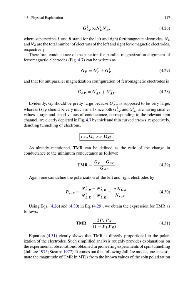
Equation (4.31) clearly shows that TMR is directly proportional to the polarization of the electrodes. Such simplified analysis roughly provides explanations on
the experimental observations, obtained in pioneering experiments of spin tunnelling
(Julliere 1975; Stearns 1977). It comes out that following Jullière model, one can estimate the magnitude of TMR in MTJs from the known values of the spin polarization
117
G
↓
AP ∞N
↓
L N
↑
R ,
(4.26)
where superscripts L and R stand for the left and right ferromagnetic electrodes. N L
and N R are the total number of electrons of the left and right ferromagnetic electrodes,
respectively.
Therefore, conductance of the junction for parallel magnetization alignment of
ferromagnetic electrodes (Fig. 4.7) can be written as
G P = G
↑
P + G
↓
P ,
(4.27)
and that for antiparallel magnetization configuration of ferromagnetic electrodes is
G AP = G
↑
AP + G
↓
AP .
(4.28)
Evidently, G p should be pretty large because G
↑
AP is supposed to be very large,
whereas G AP should be very much small since both G
↑
AP and G
↓
AP are having smaller
values. Large and small values of conductance, corresponding to the relevant spin
channel, are clearly depicted in Fig. 4.7 by thick and thin curved arrows, respectively,
denoting tunnelling of electrons.
i.e., G p >> G AP .
As already mentioned, TMR can be defined as the ratio of the change in
conductance to the minimum conductance as follows:
TMR =
G P − G AP
G AP
.
(4.29)
Again one can define the polarization of the left and right electrodes by
P L,R =
N
↑
L,R − N
↓
L,R
N
↑
L,R + N
↓
L,R
=
N L,R
N L,R
.
(4.30)
Using Eqs. (4.26) and (4.30) in Eq. (4.29), we obtain the expression for TMR as
follows:
TMR =
2 P L P R
(1 − P L P R )
.
(4.31)
Equation (4.31) clearly shows that TMR is directly proportional to the polarization of the electrodes. Such simplified analysis roughly provides explanations on
the experimental observations, obtained in pioneering experiments of spin tunnelling
(Julliere 1975; Stearns 1977). It comes out that following Jullière model, one can estimate the magnitude of TMR in MTJs from the known values of the spin polarization