

3.7 Magnetoresistance Theory
95
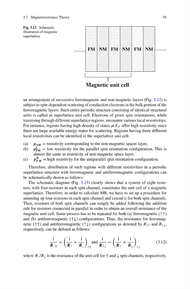
Fig. 3.12 Schematic
illustration of magnetic
superlattice
an arrangement of successive ferromagnetic and non-magnetic layers (Fig. 3.12) is
subject to spin-dependent scattering of conduction electrons in the bulk portion of the
ferromagnetic layers. Such entire periodic structure consisting of identical structural
units is called as superlattice unit cell. Electrons of given spin orientations, while
traversing through different superlattice regions, encounter various local resistivities.
For instance, regions having high density of states at E F offer high resistivity since
there are large available energy states for scattering. Regions having three different
local resistivities can be identified in the superlattice unit cell:
(a) ρ NM = resistivity corresponding to the non-magnetic spacer layer,
(b) ρ
L
FM = low resistivity for the parallel spin orientation configuration. This is
almost the same as resistivity of non-magnetic space layer.
(c) ρ
H
F M = high resistivity for the antiparallel spin orientation configuration.
Therefore, distribution of such regions with different resistivities in a periodic
superlattice structure with ferromagnetic and antiferromagnetic configurations can
be schematically drawn as follows:
The schematic diagram (Fig. 3.13) clearly shows that a system of eight resistors, with four resistors in each spin channel, constitutes the unit cell of a magnetic
superlattice. Therefore, in order to calculate MR, we have to set up a procedure for
summing up four resistors in each spin channel and extend it for both spin channels.
Then, resistors of both spin channels can simply be added following the addition
rule for resistors connected in parallel in order to obtain an overall resistance of the
magnetic unit cell. Same process has to be repeated for both (a) ferromagnetic (↑↑)
and (b) antiferromagnetic (↑↓) configurations. Thus, the resistance for ferromagnetic (↑↑) and antiferromagnetic (↑↓) configurations as denoted by R ↑↑ and R ↑↓ ,
respectively, can be defined as follows:
1
R ↑↑
=
1
R ↑
+
1
R ↓
↑↑
and
1
R ↑↓
=
1
R ↑
+
1
R ↓
↑↓
(3.12)
where R ↑ /R ↓ is the resistance of the unit cell for ↑ and ↓ spin channels, respectively.
95
Fig. 3.12 Schematic
illustration of magnetic
superlattice
an arrangement of successive ferromagnetic and non-magnetic layers (Fig. 3.12) is
subject to spin-dependent scattering of conduction electrons in the bulk portion of the
ferromagnetic layers. Such entire periodic structure consisting of identical structural
units is called as superlattice unit cell. Electrons of given spin orientations, while
traversing through different superlattice regions, encounter various local resistivities.
For instance, regions having high density of states at E F offer high resistivity since
there are large available energy states for scattering. Regions having three different
local resistivities can be identified in the superlattice unit cell:
(a) ρ NM = resistivity corresponding to the non-magnetic spacer layer,
(b) ρ
L
FM = low resistivity for the parallel spin orientation configuration. This is
almost the same as resistivity of non-magnetic space layer.
(c) ρ
H
F M = high resistivity for the antiparallel spin orientation configuration.
Therefore, distribution of such regions with different resistivities in a periodic
superlattice structure with ferromagnetic and antiferromagnetic configurations can
be schematically drawn as follows:
The schematic diagram (Fig. 3.13) clearly shows that a system of eight resistors, with four resistors in each spin channel, constitutes the unit cell of a magnetic
superlattice. Therefore, in order to calculate MR, we have to set up a procedure for
summing up four resistors in each spin channel and extend it for both spin channels.
Then, resistors of both spin channels can simply be added following the addition
rule for resistors connected in parallel in order to obtain an overall resistance of the
magnetic unit cell. Same process has to be repeated for both (a) ferromagnetic (↑↑)
and (b) antiferromagnetic (↑↓) configurations. Thus, the resistance for ferromagnetic (↑↑) and antiferromagnetic (↑↓) configurations as denoted by R ↑↑ and R ↑↓ ,
respectively, can be defined as follows:
1
R ↑↑
=
1
R ↑
+
1
R ↓
↑↑
and
1
R ↑↓
=
1
R ↑
+
1
R ↓
↑↓
(3.12)
where R ↑ /R ↓ is the resistance of the unit cell for ↑ and ↓ spin channels, respectively.