

258
12 Geometry of Moduli Spaces and Riemann Surfaces
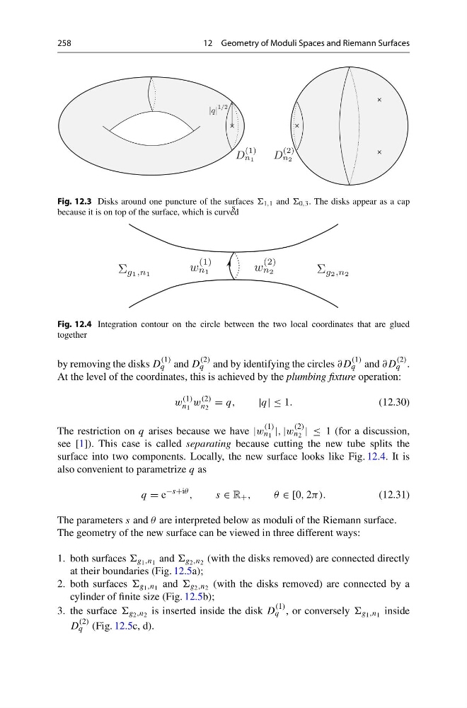
Fig. 12.3 Disks around one puncture of the surfaces 1,1 and 0,3 . The disks appear as a cap
because it is on top of the surface, which is curved
s
Fig. 12.4 Integration contour on the circle between the two local coordinates that are glued
together
by removing the disks D
(1)
q and D
(2)
q and by identifying the circles ∂D
(1)
q and ∂D
(2)
q .
At the level of the coordinates, this is achieved by the plumbing fixture operation:
w
(1)
n 1
w
(2)
n 2
= q,
|q| ≤ 1.
(12.30)
The restriction on q arises because we have |w
(1)
n 1 |, |w
(2)
n 2 | ≤ 1 (for a discussion,
see [1]). This case is called separating because cutting the new tube splits the
surface into two components. Locally, the new surface looks like Fig. 12.4. It is
also convenient to parametrize q as
q = e
−s+iθ ,
s ∈ R + ,
θ ∈ [0, 2π).
(12.31)
The parameters s and θ are interpreted below as moduli of the Riemann surface.
The geometry of the new surface can be viewed in three different ways:
1. both surfaces g 1 ,n 1 and g 2 ,n 2 (with the disks removed) are connected directly
at their boundaries (Fig. 12.5a);
2. both surfaces g 1 ,n 1 and g 2 ,n 2 (with the disks removed) are connected by a
cylinder of finite size (Fig. 12.5b);
3. the surface g 2 ,n 2 is inserted inside the disk D
(1)
q , or conversely g 1 ,n 1 inside
D
(2)
q (Fig. 12.5c, d).
12 Geometry of Moduli Spaces and Riemann Surfaces
Fig. 12.3 Disks around one puncture of the surfaces 1,1 and 0,3 . The disks appear as a cap
because it is on top of the surface, which is curved
s
Fig. 12.4 Integration contour on the circle between the two local coordinates that are glued
together
by removing the disks D
(1)
q and D
(2)
q and by identifying the circles ∂D
(1)
q and ∂D
(2)
q .
At the level of the coordinates, this is achieved by the plumbing fixture operation:
w
(1)
n 1
w
(2)
n 2
= q,
|q| ≤ 1.
(12.30)
The restriction on q arises because we have |w
(1)
n 1 |, |w
(2)
n 2 | ≤ 1 (for a discussion,
see [1]). This case is called separating because cutting the new tube splits the
surface into two components. Locally, the new surface looks like Fig. 12.4. It is
also convenient to parametrize q as
q = e
−s+iθ ,
s ∈ R + ,
θ ∈ [0, 2π).
(12.31)
The parameters s and θ are interpreted below as moduli of the Riemann surface.
The geometry of the new surface can be viewed in three different ways:
1. both surfaces g 1 ,n 1 and g 2 ,n 2 (with the disks removed) are connected directly
at their boundaries (Fig. 12.5a);
2. both surfaces g 1 ,n 1 and g 2 ,n 2 (with the disks removed) are connected by a
cylinder of finite size (Fig. 12.5b);
3. the surface g 2 ,n 2 is inserted inside the disk D
(1)
q , or conversely g 1 ,n 1 inside
D
(2)
q (Fig. 12.5c, d).