

VC95 vacuum controller board, converts a Pirani gauge output
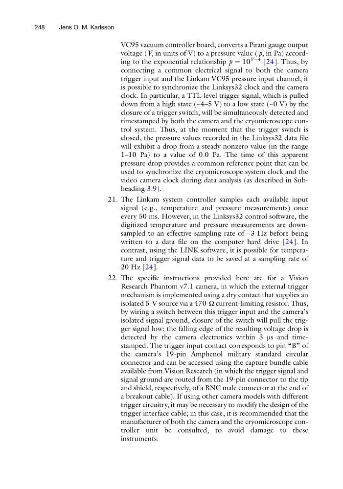
voltage (V, in units of V) to a pressure value ( p, in Pa) according to the exponential relationship p ¼ 10
VÀ4 [24]. Thus, by
connecting a common electrical signal to both the camera
trigger input and the Linkam VC95 pressure input channel, it
is possible to synchronize the Linksys32 clock and the camera
clock. In particular, a TTL-level trigger signal, which is pulled
down from a high state (~4–5 V) to a low state (~0 V) by the
closure of a trigger switch, will be simultaneously detected and
timestamped by both the camera and the cryomicroscope control system. Thus, at the moment that the trigger switch is
closed, the pressure values recorded in the Linksys32 data file
will exhibit a drop from a steady nonzero value (in the range
1–10 Pa) to a value of 0.0 Pa. The time of this apparent
pressure drop provides a common reference point that can be
used to synchronize the cryomicroscope system clock and the
video camera clock during data analysis (as described in Subheading 3.9).
21. The Linkam system controller samples each available input
signal (e.g., temperature and pressure measurements) once
every 50 ms. However, in the Linksys32 control software, the
digitized temperature and pressure measurements are downsampled to an effective sampling rate of ~3 Hz before being
written to a data file on the computer hard drive [24]. In
contrast, using the LINK software, it is possible for temperature and trigger signal data to be saved at a sampling rate of
20 Hz [24].
22. The specific instructions provided here are for a Vision
Research Phantom v7.1 camera, in which the external trigger
mechanism is implemented using a dry contact that supplies an
isolated 5-V source via a 470-Ω current-limiting resistor. Thus,
by wiring a switch between this trigger input and the camera’s
isolated signal ground, closure of the switch will pull the trigger signal low; the falling edge of the resulting voltage drop is
detected by the camera electronics within 3 μs and timestamped. The trigger input contact corresponds to pin “B” of
the camera’s 19-pin Amphenol military standard circular
connector and can be accessed using the capture bundle cable
available from Vision Research (in which the trigger signal and
signal ground are routed from the 19-pin connector to the tip
and shield, respectively, of a BNC male connector at the end of
a breakout cable). If using other camera models with different
trigger circuitry, it may be necessary to modify the design of the
trigger interface cable; in this case, it is recommended that the
manufacturer of both the camera and the cryomicroscope controller unit be consulted, to avoid damage to these
instruments.
248
Jens O. M. Karlsson
voltage (V, in units of V) to a pressure value ( p, in Pa) according to the exponential relationship p ¼ 10
VÀ4 [24]. Thus, by
connecting a common electrical signal to both the camera
trigger input and the Linkam VC95 pressure input channel, it
is possible to synchronize the Linksys32 clock and the camera
clock. In particular, a TTL-level trigger signal, which is pulled
down from a high state (~4–5 V) to a low state (~0 V) by the
closure of a trigger switch, will be simultaneously detected and
timestamped by both the camera and the cryomicroscope control system. Thus, at the moment that the trigger switch is
closed, the pressure values recorded in the Linksys32 data file
will exhibit a drop from a steady nonzero value (in the range
1–10 Pa) to a value of 0.0 Pa. The time of this apparent
pressure drop provides a common reference point that can be
used to synchronize the cryomicroscope system clock and the
video camera clock during data analysis (as described in Subheading 3.9).
21. The Linkam system controller samples each available input
signal (e.g., temperature and pressure measurements) once
every 50 ms. However, in the Linksys32 control software, the
digitized temperature and pressure measurements are downsampled to an effective sampling rate of ~3 Hz before being
written to a data file on the computer hard drive [24]. In
contrast, using the LINK software, it is possible for temperature and trigger signal data to be saved at a sampling rate of
20 Hz [24].
22. The specific instructions provided here are for a Vision
Research Phantom v7.1 camera, in which the external trigger
mechanism is implemented using a dry contact that supplies an
isolated 5-V source via a 470-Ω current-limiting resistor. Thus,
by wiring a switch between this trigger input and the camera’s
isolated signal ground, closure of the switch will pull the trigger signal low; the falling edge of the resulting voltage drop is
detected by the camera electronics within 3 μs and timestamped. The trigger input contact corresponds to pin “B” of
the camera’s 19-pin Amphenol military standard circular
connector and can be accessed using the capture bundle cable
available from Vision Research (in which the trigger signal and
signal ground are routed from the 19-pin connector to the tip
and shield, respectively, of a BNC male connector at the end of
a breakout cable). If using other camera models with different
trigger circuitry, it may be necessary to modify the design of the
trigger interface cable; in this case, it is recommended that the
manufacturer of both the camera and the cryomicroscope controller unit be consulted, to avoid damage to these
instruments.
248
Jens O. M. Karlsson