

6. Use the tip of the dispensing needle to smear the grease dots
together, to form a continuous grease circle as shown in Fig. 3b
(see Note 66).
D
E
A
B
C
CC
GR
GR
CS
CC
CC
FT
FT
WS
FT
FT
FT
FT
FT
FT
FT
FT
CC
CC
CC
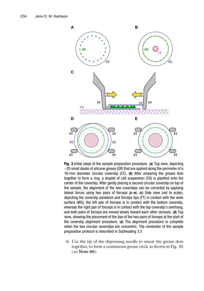
Fig. 3 Initial steps of the sample preparation procedure. (a) Top view, depicting
~20 small daubs of silicone grease (GR) that are applied along the perimeter of a
16-mm diameter circular coverslip (CC). (b) After smearing the grease dots
together to form a ring, a droplet of cell suspension (CS) is pipetted onto the
center of the coverslip. After gently placing a second circular coverslip on top of
the sample, the alignment of the two coverslips can be corrected by applying
lateral forces using two pairs of forceps (c–e). (c) Side view (not to scale),
depicting the coverslip sandwich and forceps tips (FT) in contact with the work
surface (WS); the left pair of forceps is in contact with the bottom coverslip,
whereas the right pair of forceps is in contact with the top coverslip’s overhang,
and both pairs of forceps are moved slowly toward each other (arrows). (d) Top
view, showing the placement of the tips of the two pairs of forceps at the start of
the coverslip alignment procedure. (e) The alignment procedure is complete
when the two circular coverslips are concentric. The remainder of the sample
preparation protocol is described in Subheading 3.5
234
Jens O. M. Karlsson
together, to form a continuous grease circle as shown in Fig. 3b
(see Note 66).
D
E
A
B
C
CC
GR
GR
CS
CC
CC
FT
FT
WS
FT
FT
FT
FT
FT
FT
FT
FT
CC
CC
CC
Fig. 3 Initial steps of the sample preparation procedure. (a) Top view, depicting
~20 small daubs of silicone grease (GR) that are applied along the perimeter of a
16-mm diameter circular coverslip (CC). (b) After smearing the grease dots
together to form a ring, a droplet of cell suspension (CS) is pipetted onto the
center of the coverslip. After gently placing a second circular coverslip on top of
the sample, the alignment of the two coverslips can be corrected by applying
lateral forces using two pairs of forceps (c–e). (c) Side view (not to scale),
depicting the coverslip sandwich and forceps tips (FT) in contact with the work
surface (WS); the left pair of forceps is in contact with the bottom coverslip,
whereas the right pair of forceps is in contact with the top coverslip’s overhang,
and both pairs of forceps are moved slowly toward each other (arrows). (d) Top
view, showing the placement of the tips of the two pairs of forceps at the start of
the coverslip alignment procedure. (e) The alignment procedure is complete
when the two circular coverslips are concentric. The remainder of the sample
preparation protocol is described in Subheading 3.5
234
Jens O. M. Karlsson