

BNC T
adapter
Manual trigger
pushbutton
switch
Vacuum
gauge
connector
Camera
external signal
connector
6
1
P
B
Camera capture
bundle cable
B
BNC T
adapter
Manual trigger
pushbutton
switch
A
S
S
T
T
BNC
connector
3.5 mm mono plug
to BNC adapter
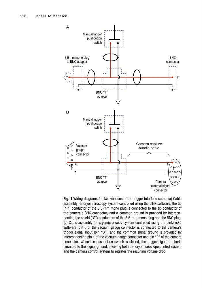
Fig. 1 Wiring diagrams for two versions of the trigger interface cable. (a) Cable
assembly for cryomicroscopy system controlled using the LINK software; the tip
(“T”) conductor of the 3.5-mm mono plug is connected to the tip conductor of
the camera’s BNC connector, and a common ground is provided by interconnecting the shield (“S”) conductors of the 3.5-mm mono plug and the BNC plug.
(b) Cable assembly for cryomicroscopy system controlled using the Linksys32
software; pin 6 of the vacuum gauge connector is connected to the camera’s
trigger signal input (pin “B”), and the common signal ground is provided by
interconnecting pin 1 of the vacuum gauge connector and pin “P” of the camera
connector. When the pushbutton switch is closed, the trigger signal is shortcircuited to the signal ground, allowing both the cryomicroscope control system
and the camera control system to register the resulting voltage drop
226
Jens O. M. Karlsson
adapter
Manual trigger
pushbutton
switch
Vacuum
gauge
connector
Camera
external signal
connector
6
1
P
B
Camera capture
bundle cable
B
BNC T
adapter
Manual trigger
pushbutton
switch
A
S
S
T
T
BNC
connector
3.5 mm mono plug
to BNC adapter
Fig. 1 Wiring diagrams for two versions of the trigger interface cable. (a) Cable
assembly for cryomicroscopy system controlled using the LINK software; the tip
(“T”) conductor of the 3.5-mm mono plug is connected to the tip conductor of
the camera’s BNC connector, and a common ground is provided by interconnecting the shield (“S”) conductors of the 3.5-mm mono plug and the BNC plug.
(b) Cable assembly for cryomicroscopy system controlled using the Linksys32
software; pin 6 of the vacuum gauge connector is connected to the camera’s
trigger signal input (pin “B”), and the common signal ground is provided by
interconnecting pin 1 of the vacuum gauge connector and pin “P” of the camera
connector. When the pushbutton switch is closed, the trigger signal is shortcircuited to the signal ground, allowing both the cryomicroscope control system
and the camera control system to register the resulting voltage drop
226
Jens O. M. Karlsson