

56
2 The Interaction of Electromagnetic Waves with Water
(1)
(2)
(3)
10
0
10
3
10
6
10
9
10
12
10
15
10
18
Radiowaves
Microwaves
IR
Vis. UV, X-rays
Frequency (Hz)
Autobalanced bridge
(1)
Reflection
(2)
TDS
(3)
FTIR
(3)
Absorption
(4)
(4)
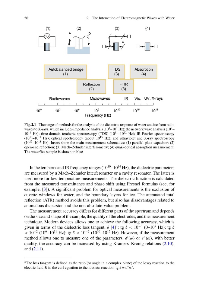
Fig. 2.1 The range of methods for the analysis of the dielectric response of water and ice from radio
waves to X-rays, which includes impedance analysis (10 1 –10 7 Hz); the network wave analysis (10 7 –
10 11 Hz); time-domain terahertz spectroscopy (TDS) (10 11 –10 12 Hz); IR-Fourier spectroscopy
(10 13 –10 14 Hz); optical spectroscopy (about 10 15 Hz); and ultraviolet and X-ray spectroscopy
(10 15 –10 18 Hz). Insets show the main measurement schematics: (1) parallel-plate capacitor; (2)
open-end reflection; (3) Mach–Zehnder interferometry; (4) quasi-optical absorption measurement.
The water/ice sample is shown in blue
In the terahertz and IR frequency ranges (10
10 –10
14 Hz), the dielectric parameters
are measured by a Mach–Zehnder interferometer or a cavity resonator. The latter is
used more for low-temperature measurements. The dielectric function is calculated
from the measured transmittance and phase shift using Fresnel formulas (see, for
example, [3]). A significant problem for optical measurements is the exclusion of
cuvette windows for water, and the boundary layers for ice. The attenuated total
reflection (ATR) method avoids this problem, but also has disadvantages related to
anomalous dispersion and the non-absolute-value problem.
The measurement accuracy differs for different parts of the spectrum and depends
on the size and shape of the sample, the quality of the electrodes, and the measurement
technique. Modern devices allows one to achieve the following accuracy, which is
given in terms of the dielectric loss tangent, δ [4]
3 : tg δ < 10
−3 (0–10
7 Hz); tg δ
< 10
−2 (10
6 –10
11 Hz); tg δ < 10
−2 (10
10 –10
15 Hz). However, if the measurement
method allows one to measure one of the parameters,
(ω) or with better
quality, the accuracy can be increased by using Kramers–Kronig relations (2.10),
and (2.11).
3 The loss tangent is defined as the ratio (or angle in a complex plane) of the lossy reaction to the
electric field E in the curl equation to the lossless reaction: tg δ = / .
2 The Interaction of Electromagnetic Waves with Water
(1)
(2)
(3)
10
0
10
3
10
6
10
9
10
12
10
15
10
18
Radiowaves
Microwaves
IR
Vis. UV, X-rays
Frequency (Hz)
Autobalanced bridge
(1)
Reflection
(2)
TDS
(3)
FTIR
(3)
Absorption
(4)
(4)
Fig. 2.1 The range of methods for the analysis of the dielectric response of water and ice from radio
waves to X-rays, which includes impedance analysis (10 1 –10 7 Hz); the network wave analysis (10 7 –
10 11 Hz); time-domain terahertz spectroscopy (TDS) (10 11 –10 12 Hz); IR-Fourier spectroscopy
(10 13 –10 14 Hz); optical spectroscopy (about 10 15 Hz); and ultraviolet and X-ray spectroscopy
(10 15 –10 18 Hz). Insets show the main measurement schematics: (1) parallel-plate capacitor; (2)
open-end reflection; (3) Mach–Zehnder interferometry; (4) quasi-optical absorption measurement.
The water/ice sample is shown in blue
In the terahertz and IR frequency ranges (10
10 –10
14 Hz), the dielectric parameters
are measured by a Mach–Zehnder interferometer or a cavity resonator. The latter is
used more for low-temperature measurements. The dielectric function is calculated
from the measured transmittance and phase shift using Fresnel formulas (see, for
example, [3]). A significant problem for optical measurements is the exclusion of
cuvette windows for water, and the boundary layers for ice. The attenuated total
reflection (ATR) method avoids this problem, but also has disadvantages related to
anomalous dispersion and the non-absolute-value problem.
The measurement accuracy differs for different parts of the spectrum and depends
on the size and shape of the sample, the quality of the electrodes, and the measurement
technique. Modern devices allows one to achieve the following accuracy, which is
given in terms of the dielectric loss tangent, δ [4]
3 : tg δ < 10
−3 (0–10
7 Hz); tg δ
< 10
−2 (10
6 –10
11 Hz); tg δ < 10
−2 (10
10 –10
15 Hz). However, if the measurement
method allows one to measure one of the parameters,
(ω) or with better
quality, the accuracy can be increased by using Kramers–Kronig relations (2.10),
and (2.11).
3 The loss tangent is defined as the ratio (or angle in a complex plane) of the lossy reaction to the
electric field E in the curl equation to the lossless reaction: tg δ = / .