

66
3 SAMPA Chip Implementation
T00 T01 T02 T03 T04 T05 T06 T07 T08 T09 T10 T11 T12 T13 T14
S00 S01 S02 S03 S04 S05 S06 S07 S08 S09 S10 S11 S12 S13 S14
Threshold
ADC SAMPLES
TIME
SAMPLES
S02 S03 S04 S05 S06
S10 S11 S12
Cluster data
(10-bit Words)
Data in memory
(not to scale)
T02
05
T10
03
Cluster information
(10-bit Words)
Header
05, T02, S02, S03, S04, S05, S06, 03, T10, S10, S11, S12
Data and information
packed into memory
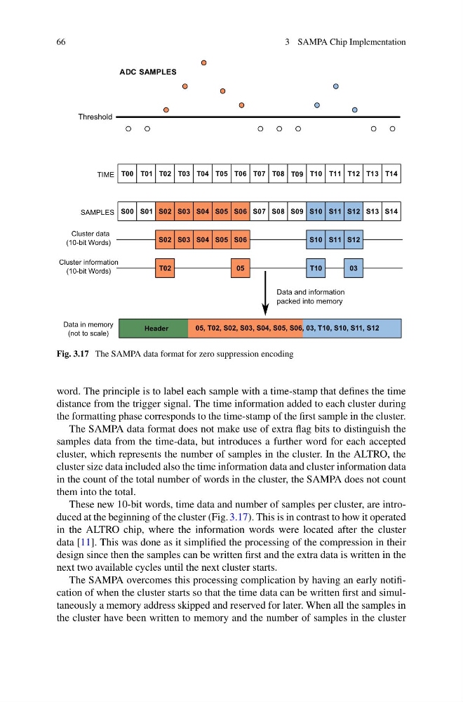
Fig. 3.17 The SAMPA data format for zero suppression encoding
word. The principle is to label each sample with a time-stamp that defines the time
distance from the trigger signal. The time information added to each cluster during
the formatting phase corresponds to the time-stamp of the first sample in the cluster.
The SAMPA data format does not make use of extra flag bits to distinguish the
samples data from the time-data, but introduces a further word for each accepted
cluster, which represents the number of samples in the cluster. In the ALTRO, the
cluster size data included also the time information data and cluster information data
in the count of the total number of words in the cluster, the SAMPA does not count
them into the total.
These new 10-bit words, time data and number of samples per cluster, are introduced at the beginning of the cluster (Fig. 3.17). This is in contrast to how it operated
in the ALTRO chip, where the information words were located after the cluster
data [11]. This was done as it simplified the processing of the compression in their
design since then the samples can be written first and the extra data is written in the
next two available cycles until the next cluster starts.
The SAMPA overcomes this processing complication by having an early notification of when the cluster starts so that the time data can be written first and simultaneously a memory address skipped and reserved for later. When all the samples in
the cluster have been written to memory and the number of samples in the cluster
3 SAMPA Chip Implementation
T00 T01 T02 T03 T04 T05 T06 T07 T08 T09 T10 T11 T12 T13 T14
S00 S01 S02 S03 S04 S05 S06 S07 S08 S09 S10 S11 S12 S13 S14
Threshold
ADC SAMPLES
TIME
SAMPLES
S02 S03 S04 S05 S06
S10 S11 S12
Cluster data
(10-bit Words)
Data in memory
(not to scale)
T02
05
T10
03
Cluster information
(10-bit Words)
Header
05, T02, S02, S03, S04, S05, S06, 03, T10, S10, S11, S12
Data and information
packed into memory
Fig. 3.17 The SAMPA data format for zero suppression encoding
word. The principle is to label each sample with a time-stamp that defines the time
distance from the trigger signal. The time information added to each cluster during
the formatting phase corresponds to the time-stamp of the first sample in the cluster.
The SAMPA data format does not make use of extra flag bits to distinguish the
samples data from the time-data, but introduces a further word for each accepted
cluster, which represents the number of samples in the cluster. In the ALTRO, the
cluster size data included also the time information data and cluster information data
in the count of the total number of words in the cluster, the SAMPA does not count
them into the total.
These new 10-bit words, time data and number of samples per cluster, are introduced at the beginning of the cluster (Fig. 3.17). This is in contrast to how it operated
in the ALTRO chip, where the information words were located after the cluster
data [11]. This was done as it simplified the processing of the compression in their
design since then the samples can be written first and the extra data is written in the
next two available cycles until the next cluster starts.
The SAMPA overcomes this processing complication by having an early notification of when the cluster starts so that the time data can be written first and simultaneously a memory address skipped and reserved for later. When all the samples in
the cluster have been written to memory and the number of samples in the cluster