

14
2 Front-End Electronics
ADC
10
First Baseline
Correction
Pedestal
Memory
11
2'sC
3rd Order
Digital Filter
Second
Baseline
Correction
Zero
Suppression
Data Format
Multi - Event
Buffer
11
2'sC
11
2'sC
11
2'sC
40
Data
Memory
Configuration
and Status
Registers
Bus
Interface
Trigger
Manager
tw
L1
L2
DATA PROCESSOR
BD CTRL
ACQUISITION CHANNEL (×16)
COMMON
CONTROL
LOGIC
+
–
Runs with Sampling Clock
Runs with Readout Clock
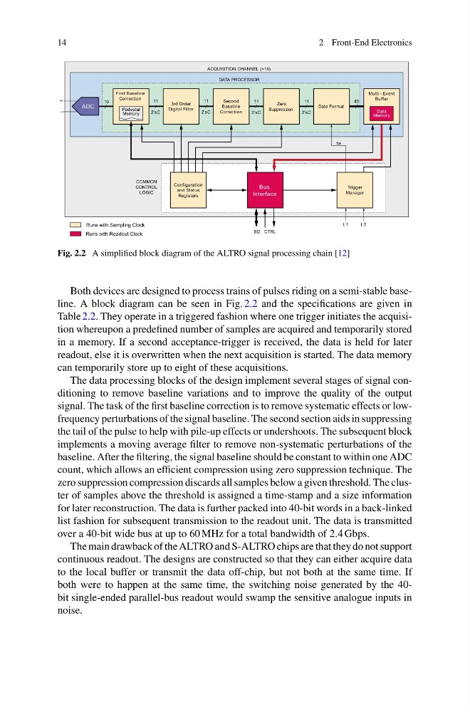
Fig. 2.2 A simplified block diagram of the ALTRO signal processing chain [12]
Both devices are designed to process trains of pulses riding on a semi-stable baseline. A block diagram can be seen in Fig. 2.2 and the specifications are given in
Table 2.2. They operate in a triggered fashion where one trigger initiates the acquisition whereupon a predefined number of samples are acquired and temporarily stored
in a memory. If a second acceptance-trigger is received, the data is held for later
readout, else it is overwritten when the next acquisition is started. The data memory
can temporarily store up to eight of these acquisitions.
The data processing blocks of the design implement several stages of signal conditioning to remove baseline variations and to improve the quality of the output
signal. The task of the first baseline correction is to remove systematic effects or lowfrequency perturbations of the signal baseline. The second section aids in suppressing
the tail of the pulse to help with pile-up effects or undershoots. The subsequent block
implements a moving average filter to remove non-systematic perturbations of the
baseline. After the filtering, the signal baseline should be constant to within one ADC
count, which allows an efficient compression using zero suppression technique. The
zero suppression compression discards all samples below a given threshold. The cluster of samples above the threshold is assigned a time-stamp and a size information
for later reconstruction. The data is further packed into 40-bit words in a back-linked
list fashion for subsequent transmission to the readout unit. The data is transmitted
over a 40-bit wide bus at up to 60 MHz for a total bandwidth of 2.4 Gbps.
The main drawback of the ALTRO and S-ALTRO chips are that they do not support
continuous readout. The designs are constructed so that they can either acquire data
to the local buffer or transmit the data off-chip, but not both at the same time. If
both were to happen at the same time, the switching noise generated by the 40bit single-ended parallel-bus readout would swamp the sensitive analogue inputs in
noise.
2 Front-End Electronics
ADC
10
First Baseline
Correction
Pedestal
Memory
11
2'sC
3rd Order
Digital Filter
Second
Baseline
Correction
Zero
Suppression
Data Format
Multi - Event
Buffer
11
2'sC
11
2'sC
11
2'sC
40
Data
Memory
Configuration
and Status
Registers
Bus
Interface
Trigger
Manager
tw
L1
L2
DATA PROCESSOR
BD CTRL
ACQUISITION CHANNEL (×16)
COMMON
CONTROL
LOGIC
+
–
Runs with Sampling Clock
Runs with Readout Clock
Fig. 2.2 A simplified block diagram of the ALTRO signal processing chain [12]
Both devices are designed to process trains of pulses riding on a semi-stable baseline. A block diagram can be seen in Fig. 2.2 and the specifications are given in
Table 2.2. They operate in a triggered fashion where one trigger initiates the acquisition whereupon a predefined number of samples are acquired and temporarily stored
in a memory. If a second acceptance-trigger is received, the data is held for later
readout, else it is overwritten when the next acquisition is started. The data memory
can temporarily store up to eight of these acquisitions.
The data processing blocks of the design implement several stages of signal conditioning to remove baseline variations and to improve the quality of the output
signal. The task of the first baseline correction is to remove systematic effects or lowfrequency perturbations of the signal baseline. The second section aids in suppressing
the tail of the pulse to help with pile-up effects or undershoots. The subsequent block
implements a moving average filter to remove non-systematic perturbations of the
baseline. After the filtering, the signal baseline should be constant to within one ADC
count, which allows an efficient compression using zero suppression technique. The
zero suppression compression discards all samples below a given threshold. The cluster of samples above the threshold is assigned a time-stamp and a size information
for later reconstruction. The data is further packed into 40-bit words in a back-linked
list fashion for subsequent transmission to the readout unit. The data is transmitted
over a 40-bit wide bus at up to 60 MHz for a total bandwidth of 2.4 Gbps.
The main drawback of the ALTRO and S-ALTRO chips are that they do not support
continuous readout. The designs are constructed so that they can either acquire data
to the local buffer or transmit the data off-chip, but not both at the same time. If
both were to happen at the same time, the switching noise generated by the 40bit single-ended parallel-bus readout would swamp the sensitive analogue inputs in
noise.