

The whole circuit adopts a multistage decompression method to avoid the problem
of chip heating caused by excessive voltage drop. 220 V power supply connects with
the power input port (IN). The voltage is reduced to 5 V by isolated AC–DC step-down
module (P1) and then to 3.3 V by AMS117 (U1). After each step-down, the power
supply needs to be filtered to make the generated voltage more stable, so as to supply
power to other modules.
3.3 Smoke Monitoring Circuit
Sensor technology, as the main technology in the Internet of things, has become an
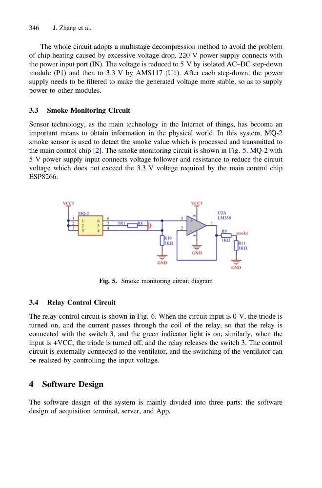
important means to obtain information in the physical world. In this system, MQ-2
smoke sensor is used to detect the smoke value which is processed and transmitted to
the main control chip [2]. The smoke monitoring circuit is shown in Fig. 5. MQ-2 with
5 V power supply input connects voltage follower and resistance to reduce the circuit
voltage which does not exceed the 3.3 V voltage required by the main control chip
ESP8266.
3.4 Relay Control Circuit
The relay control circuit is shown in Fig. 6. When the circuit input is 0 V, the triode is
turned on, and the current passes through the coil of the relay, so that the relay is
connected with the switch 3, and the green indicator light is on; similarly, when the
input is +VCC, the triode is turned off, and the relay releases the switch 3. The control
circuit is externally connected to the ventilator, and the switching of the ventilator can
be realized by controlling the input voltage.
4 Software Design
The software design of the system is mainly divided into three parts: the software
design of acquisition terminal, server, and App.
Fig. 5. Smoke monitoring circuit diagram
346
J. Zhang et al.
of chip heating caused by excessive voltage drop. 220 V power supply connects with
the power input port (IN). The voltage is reduced to 5 V by isolated AC–DC step-down
module (P1) and then to 3.3 V by AMS117 (U1). After each step-down, the power
supply needs to be filtered to make the generated voltage more stable, so as to supply
power to other modules.
3.3 Smoke Monitoring Circuit
Sensor technology, as the main technology in the Internet of things, has become an
important means to obtain information in the physical world. In this system, MQ-2
smoke sensor is used to detect the smoke value which is processed and transmitted to
the main control chip [2]. The smoke monitoring circuit is shown in Fig. 5. MQ-2 with
5 V power supply input connects voltage follower and resistance to reduce the circuit
voltage which does not exceed the 3.3 V voltage required by the main control chip
ESP8266.
3.4 Relay Control Circuit
The relay control circuit is shown in Fig. 6. When the circuit input is 0 V, the triode is
turned on, and the current passes through the coil of the relay, so that the relay is
connected with the switch 3, and the green indicator light is on; similarly, when the
input is +VCC, the triode is turned off, and the relay releases the switch 3. The control
circuit is externally connected to the ventilator, and the switching of the ventilator can
be realized by controlling the input voltage.
4 Software Design
The software design of the system is mainly divided into three parts: the software
design of acquisition terminal, server, and App.
Fig. 5. Smoke monitoring circuit diagram
346
J. Zhang et al.