

and tracking are needed to accommodate the movement of UAVs [6]. Good beam
shape is also desired to improve the data rate of covered region.
In [7], a novel capacity enhancement method for small cells utilizing the flexible
three-dimensional (3D) beamforming facilitated by adoption of the active antenna
system (AAS) at base stations (BSs) is proposed. In contrast to conventional microcell
networks, significant gain of capacity has been achieved by using this novel method.
However, this dynamic and flexible 3D beamforming with narrow beamwidth is only
feasible in the small cell layer. In [8], the authors took the coverage and rate performance of mmWave cellular networks into account, which leads to higher peak rates
while didn’t improve the cell edge rates. To guarantee a good tradeoff between the rates
of center and edge, a novel wide beam design method combined with orthogonal
matching pursuit (OMP) algorithm was proposed in [9]. The work [10] proposed an
optimized beam by combining the quantification of spatial angle and the improved
OMP algorithm. Literature [11] proposed solution relies on the gradient pursuit
(GP) algorithm to fast approximation the optimal digital precoding. However, all the
methods mentioned above had high system complexity.
This paper aims to fill these gaps. The major contributions and novelties of this
paper are summarized as follows:
(1) To achieve better beam coverage performance, the expression of the equivalent
channel is derived by using the principle of singular value decomposition (SVD).
(2) To obtain the ideal hybrid precoding vector according to the expected beam gain,
the target region is quantified and the sparse state matrix is established.
(3) A precoding algorithm based on DDL-OMP is presented. The new method can
reduce the system complexity while improving the communication capacity.
2 System Model
In this paper, a downlink UAV-BS with mmWave hybrid beamforming system is
considered. Both the transmitter and receiver are equipped with UPA of M MS ¼
M BS ¼ M h  M v antennas. The array is laid out in a grid pattern with M h columns and
M v rows [9], where the distance between antenna elements is spaced uniformly with
separations d h and d v , respectively [12].
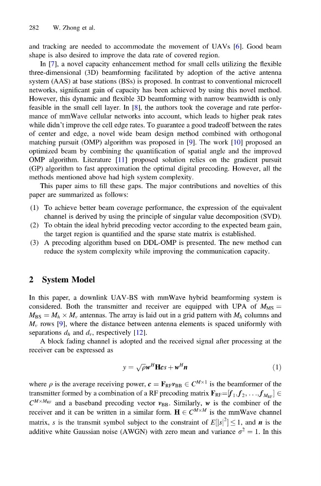
A block fading channel is adopted and the received signal after processing at the
receiver can be expressed as
y ¼
ffiffiffi
q
p w
H Hcs þ w
H
n
ð1Þ
where q is the average receiving power, c ¼ F RF v BB 2 C
MÂ1 is the beamformer of the
transmitter formed by a combination of a RF precoding matrix F RF ¼ f 1 ; f 2 ;
½
. . .; f M RF 2
C
MÂM RF and a baseband precoding vector v BB . Similarly, w is the combiner of the
receiver and it can be written in a similar form. H 2 C
MÂM is the mmWave channel
matrix, s is the transmit symbol subject to the constraint of E½jsj
2 1, and n is the
additive white Gaussian noise (AWGN) with zero mean and variance r
2
¼ 1. In this
282
W. Zhong et al.
shape is also desired to improve the data rate of covered region.
In [7], a novel capacity enhancement method for small cells utilizing the flexible
three-dimensional (3D) beamforming facilitated by adoption of the active antenna
system (AAS) at base stations (BSs) is proposed. In contrast to conventional microcell
networks, significant gain of capacity has been achieved by using this novel method.
However, this dynamic and flexible 3D beamforming with narrow beamwidth is only
feasible in the small cell layer. In [8], the authors took the coverage and rate performance of mmWave cellular networks into account, which leads to higher peak rates
while didn’t improve the cell edge rates. To guarantee a good tradeoff between the rates
of center and edge, a novel wide beam design method combined with orthogonal
matching pursuit (OMP) algorithm was proposed in [9]. The work [10] proposed an
optimized beam by combining the quantification of spatial angle and the improved
OMP algorithm. Literature [11] proposed solution relies on the gradient pursuit
(GP) algorithm to fast approximation the optimal digital precoding. However, all the
methods mentioned above had high system complexity.
This paper aims to fill these gaps. The major contributions and novelties of this
paper are summarized as follows:
(1) To achieve better beam coverage performance, the expression of the equivalent
channel is derived by using the principle of singular value decomposition (SVD).
(2) To obtain the ideal hybrid precoding vector according to the expected beam gain,
the target region is quantified and the sparse state matrix is established.
(3) A precoding algorithm based on DDL-OMP is presented. The new method can
reduce the system complexity while improving the communication capacity.
2 System Model
In this paper, a downlink UAV-BS with mmWave hybrid beamforming system is
considered. Both the transmitter and receiver are equipped with UPA of M MS ¼
M BS ¼ M h  M v antennas. The array is laid out in a grid pattern with M h columns and
M v rows [9], where the distance between antenna elements is spaced uniformly with
separations d h and d v , respectively [12].
A block fading channel is adopted and the received signal after processing at the
receiver can be expressed as
y ¼
ffiffiffi
q
p w
H Hcs þ w
H
n
ð1Þ
where q is the average receiving power, c ¼ F RF v BB 2 C
MÂ1 is the beamformer of the
transmitter formed by a combination of a RF precoding matrix F RF ¼ f 1 ; f 2 ;
½
. . .; f M RF 2
C
MÂM RF and a baseband precoding vector v BB . Similarly, w is the combiner of the
receiver and it can be written in a similar form. H 2 C
MÂM is the mmWave channel
matrix, s is the transmit symbol subject to the constraint of E½jsj
2 1, and n is the
additive white Gaussian noise (AWGN) with zero mean and variance r
2
¼ 1. In this
282
W. Zhong et al.