

Appendix: Interphase Dimension Measurement Via AFM
167
NBC
tHk1
tHk2
A
B
kth plane
4nm
Hk NBC
Hk Interphase
(b)
tLj
2
LjInterphase
tLj
L j NBC
A
B
jth plane
10nm
NBC
Interphase
(a)
Interphase
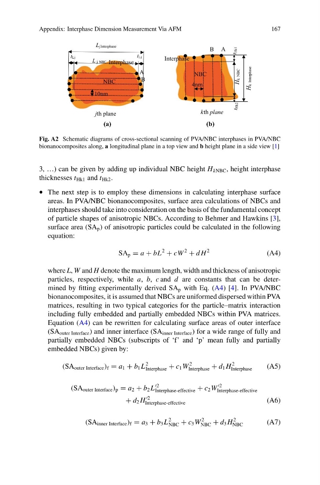
Fig. A2 Schematic diagrams of cross-sectional scanning of PVA/NBC interphases in PVA/NBC
bionanocomposites along, a longitudinal plane in a top view and b height plane in a side view [1]
3, …) can be given by adding up individual NBC height H kNBC , height interphase
thicknesses t Hk1 and t Hk2 .
• The next step is to employ these dimensions in calculating interphase surface
areas. In PVA/NBC bionanocomposites, surface area calculations of NBCs and
interphases should take into consideration on the basis of the fundamental concept
of particle shapes of anisotropic NBCs. According to Behmer and Hawkins [3],
surface area (SA p ) of anisotropic particles could be calculated in the following
equation:
SA p = a + bL
2
+ cW
2
+ d H
2
(A4)
where L, W and H denote the maximum length, width and thickness of anisotropic
particles, respectively, while a, b, c and d are constants that can be determined by fitting experimentally derived SA p with Eq. (A4) [4]. In PVA/NBC
bionanocomposites, it is assumed that NBCs are uniformed dispersed within PVA
matrices, resulting in two typical categories for the particle–matrix interaction
including fully embedded and partially embedded NBCs within PVA matrices.
Equation (A4) can be rewritten for calculating surface areas of outer interface
(SA outer Interface ) and inner interface (SA inner Interface ) for a wide range of fully and
partially embedded NBCs (subscripts of ‘f’ and ‘p’ mean fully and partially
embedded NBCs) given by:
(SA outer Interface ) f = a 1 + b 1 L
2
Interphase + c 1 W
2
Interphase + d 1 H
2
Interphase
(A5)
(SA outer Interface ) p = a 2 + b 2 L
Interphase-effective + c 2 W
Interphase-effective
+ d 2 H
Interphase-effective
(A6)
(SA inner Interface ) f = a 3 + b 3 L
2
NBC + c 3 W
2
NBC + d 3 H
2
NBC
(A7)
167
NBC
tHk1
tHk2
A
B
kth plane
4nm
Hk NBC
Hk Interphase
(b)
tLj
2
LjInterphase
tLj
L j NBC
A
B
jth plane
10nm
NBC
Interphase
(a)
Interphase
Fig. A2 Schematic diagrams of cross-sectional scanning of PVA/NBC interphases in PVA/NBC
bionanocomposites along, a longitudinal plane in a top view and b height plane in a side view [1]
3, …) can be given by adding up individual NBC height H kNBC , height interphase
thicknesses t Hk1 and t Hk2 .
• The next step is to employ these dimensions in calculating interphase surface
areas. In PVA/NBC bionanocomposites, surface area calculations of NBCs and
interphases should take into consideration on the basis of the fundamental concept
of particle shapes of anisotropic NBCs. According to Behmer and Hawkins [3],
surface area (SA p ) of anisotropic particles could be calculated in the following
equation:
SA p = a + bL
2
+ cW
2
+ d H
2
(A4)
where L, W and H denote the maximum length, width and thickness of anisotropic
particles, respectively, while a, b, c and d are constants that can be determined by fitting experimentally derived SA p with Eq. (A4) [4]. In PVA/NBC
bionanocomposites, it is assumed that NBCs are uniformed dispersed within PVA
matrices, resulting in two typical categories for the particle–matrix interaction
including fully embedded and partially embedded NBCs within PVA matrices.
Equation (A4) can be rewritten for calculating surface areas of outer interface
(SA outer Interface ) and inner interface (SA inner Interface ) for a wide range of fully and
partially embedded NBCs (subscripts of ‘f’ and ‘p’ mean fully and partially
embedded NBCs) given by:
(SA outer Interface ) f = a 1 + b 1 L
2
Interphase + c 1 W
2
Interphase + d 1 H
2
Interphase
(A5)
(SA outer Interface ) p = a 2 + b 2 L
Interphase-effective + c 2 W
Interphase-effective
+ d 2 H
Interphase-effective
(A6)
(SA inner Interface ) f = a 3 + b 3 L
2
NBC + c 3 W
2
NBC + d 3 H
2
NBC
(A7)